


Conveying System Mechanical Components Chapter 3: Installation 66 of 138
3-6 Electrical Connections
Refer to local electrical codes, the schematic, and connection diagrams supplied with this unit
and the serial tag for wiring considerations. Run all wiring in conduit if codes require it.
Label all wiring to make any future troubleshooting easier. Make all electrical connections
tight.
Making ACA Series Filter Chamber Electrical Connections
WARNING! Be safety conscious!
High or low voltage can cause serious or fatal injury.
Installation must be performed by qualified personnel only!!
Always disconnect power source before attempting installation or repair.
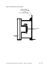
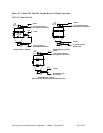
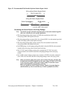
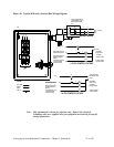
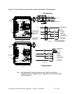
Mount the control box in any convenient location free from excessive vibration where the
temperature does not exceed 120ºF (49ºC). Power supply and solenoids are 115/1/60 for
Models 91/93, 131/133, and 251/253 ACA filter chambers; choice of 115 VAC, 230 VAC or
24 VDC on 51/53 models. Locate the power supply terminal inside the control enclosure.
Provide a hole as needed for the power supply cord and connect to L1, L2, and ground. See
the electrical schematic wiring diagram supplied in your Customer Information Packet for
more information.
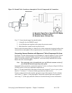
Provide another hole in the control enclosure for wiring the solenoid valves on the filter
chamber. Locate the terminal strip inside the control enclosure and connect the solenoid valve
wiring in the order shown in the electrical schematic wiring diagram supplied in your
Customer Information Packet. The order of wiring determines the sequence of the filter bag
cleaning air pulses.
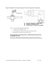
Making Pump Power Drop Wiring Connections
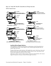
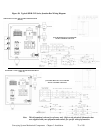
Pump packages are connected to a three-phase power supply. Bring properly sized power
leads in conduit to the contacts in the junction box of each pump package in the system.
Complete the pump wiring connections by performing the following:
• Install a properly-sized fused disconnect switch with lockout on the main lines to each
vacuum pump package. This is recommended even for pumps with optional fused
disconnects.
• Check the serial tag for voltage and amperage requirements. On 60 Hz units, voltage
supplied to the unit must be within plus or minus ten percent (±10%) of the serial tag
value; on 50 Hz units, within plus or minus five percent (±5%) of the serial tag value.
Phase imbalance must be less than 2% in accordance with NEMA MG1-14.32.
• Ground the unit for operator safety and equipment protection.
Making Control Panel Power Drop Wiring Connections
Plug the controllers’ power cord into a properly grounded, 3-slot, 115/1/60 VAC or 230/1/60
VAC receptacle as specified on the control panel serial tag and the enclosed controller
Operation and Instruction manual. The control enclosure draws less than 5 amps during
normal operation at 115/1/60 VAC.