


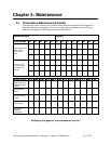
Conveying System Mechanical Components Chapter 5: Maintenance 85 of 138
5. Check compressed air supply in-line filters and clean or replace as needed.
If moisture is condensing inside the filter chamber, you may need to insulate the
chamber and the piping leading to the filter. This action should keep the surface
moisture above the dew point and prevent condensation on filter bags.
6. Do not attempt to wash or reuse soiled ACA filter bags. If they are clogged, replace
them with new filter bags. Contact the Parts Department for more information on
replacement filter bags.
7. Inspect the filter bags for wear. Thinning bags may not stop fine dust when flexed
with compressed air, or dust can escape into the clean air tank section and
contaminate conveying air. Replace with new filter bags as needed.
Note: When re-installing ACA Series filter bags, make sure that the bag is turned
inside out, with the glazed surface facing outward.
8. Carefully slip the bag over the bag cage. Position the filter bag all the way onto the
bag cage, and place a clamp around the bag near the top of the bag rack plate.
Tighten the clamp.
Note: Improperly installed clamps cause a poor dust seal.
Dusting in the clean air exhaust is a normal condition after installing new
filter bags, and should stop after the first several hours of operation.
9. Replace the upper tank section, with the gasket properly seated between upper and
lower sections. Make sure the filter bags are hanging straight down and that the bags
do not touch each other or the inside walls of the filter chamber. This action prevents
excessive bag wear when compressed air pulses enter the bags.
10. Replace and tighten the stretch clamp.
Maintaining SPDB Series Vacuum Power Unit Non-Reversing Valves
Upper and lower non-reversing valves require periodic service to keep SPDB Series vacuum
power units operating at peak efficiency. Contact the Parts Department for information on
valve service kits and customer-recommended parts.
Maintaining Upper Valves -5 to 15 HP (3.73-11.19 kW) SPDB Units
(See Valve Assembly Drawings and Spare Parts Lists in Figures 47-48)
Removing Upper Valves
1. Turn off and lock out the power switch for the vacuum power unit. Disconnect and
lock out the power main to the unit; make sure to follow applicable safety
regulations.
2. Turn off compressed air. Disconnect the compressed air line running to the pressure
relief regulator.
3. Loosen the hose clamps that connect the upper valve to the incoming vacuum line
and lower valve, and slide the hose back.
4. Loosen the set screws that secure the valve to the blower inlet.
5. Remove the valve from the power unit.