


Conveying System Mechanical Components Chapter 3: Installation 58 of 138
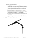
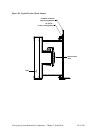
Flange Mount Vacuum Receiver Mounting
These units are designed to fit in existing equipment with standard 10” mounting holes that
will accept our vacuum receivers.
þ For new installations, the recommended cut-out is a 10” (25.4 mm) –diameter round
hole with six (6) mounting holes equally spaced on an 11.0” (279.4 mm) OD bolt
circle. The factory provides 5/16” holes on the mounting flange to allow proper bolt
clearance.
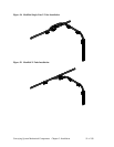
Orienting the Unit
The factory provides (12) mounting holes locations on the 11.0” (279.4 mm) OD mounting
bolt circle. Under most conditions, using six (6) of the mounting holes with the proper
hardware is sufficient to secure the unit to other equipment.
þ Make sure that mounting hardware is equally spaced along the bolt circle.
The twelve holes on the mounting bolt circle let you rotate the unit in 30 degree increments to
match the orientation of piping and wiring of the equipment.
Note: If you need a finer orientation or if you need to adjust the mounting position,
locate the six holes on the inside of the mounting flange ring.
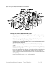
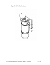
To allow for better orientation of equipment installations, the junction box bracket (located
on the mounting flange) has been designed to mount during installation by utilizing two of
the mounting locations along the bolt circle.
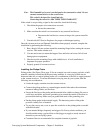
To mount the junction box assembly:
1. Mount the vacuum receiver using four (4) of the six (6) bolts.
2. Cut the temporary straps securing the junction box assembly to the mounting flange.
3. Orient the junction box assembly along the mounting bolt circle location.
Stop when the location most closely matches the preferred installation orientation.
The mounting holes for the junction box bracket must line up with two of the holes
on the mounting bolt circle flange.
Be careful of wiring on or around the unit.
4. Secure the junction box assembly with hardware through the remaining two (2)
mounting flange holes. Properly tighten to secure the assembly to the flange.
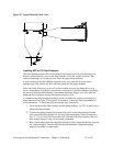
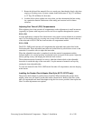
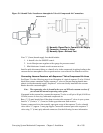
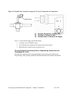
Positioning and Spacing on the Demand Switch
The factory has pre-set the demand switch position for proper operation and, under most
operating conditions, does not require adjustment.
The demand switch has two wires to provide for a normally open signal to the central
controller (close to the load):
• A common (black) contact, and
• A closed (white) contact
The demand switch sends a signal to the central controller when the material discharge
flapper is closed and the unit calls for material.
Most controllers utilize a closed contact to signal the conveying system controller that a
material demand condition exists (using the black and white wires).