


Conveying System Mechanical Components Chapter 3: Installation 57 of 138
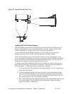
3-3 Compressed Air Blowback Connection
To provide proper filter element cleaning, the compressed air supply must be regulated to 80
PSI (5.5 bars). Low air pressure will cause poor filter element cleaning. Air consumption
depends on the frequency and length of cleaning air pulses into the filter element.
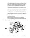
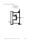
Connect a minimum of 3/8” (9 mm) air line to the top of the solenoid valve air block.
Compressed air must be clean, dry, and free of oil. A filter regulator and shut-off are
recommended components of your in-plant air supply. In-line filters can handle small
amounts of moisture; in-line desiccant filters or packed beds of granular absorbing polymer
can remove oil mist and condensed oil.
You may need to install an accumulator in your air supply system to enhance blowback
effectiveness if your system cannot consistently meet these requirements. Make sure you
use full-sized 3/8” or larger diameter pipe or tubing when making the connection.
3-4 Implosion Blowback Connection
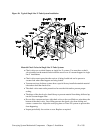
The clearing valve (implosion blowback valve) is located on the outlet of the vacuum
filter. Connect the clearing valve to a 60-80 PSI (4.1-5.5 Bar) compressed air supply.
Compressed air must be clean, dry and free of oil.
Run a 3/8” (9 mm) branch line to supply the vacuum hoppers in your system. Install a 3/8”
(9 mm) x 1/8” (3 mm) tee valve in the up position near the filter chamber.
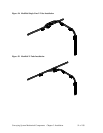
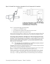
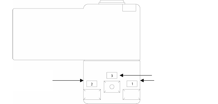
Connect shop compressed air to port number 3 on the clearing valve solenoid with 1/4”
(approx. 6 mm) poly tubing. Connect port number 2 to the clearing valve. Port 1 is to be
exhausted to the atmosphere. (See Figure 29 below).
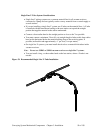
The 3/8” (9 mm) branch supply line should include a shut-off valve for on/off control, an air
filter/pressure regulator with a gauge for pressure control, and mini-lubricators located at
each vacuum receiver. Install a quick-disconnect fitting or a shut-off valve in the
compressed air piping leading to the vacuum receiver’s clearing valve to speed receiver
cover removal for cleanout or service.
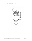
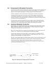
Figure 29: Clearing Valve Compressed Air Connections
Port 3: Shop Air In
Port 1: Exhaust
Port 2: (common)
Attach to Clearing
Valve