


Conveying System Mechanical Components Chapter 3: Installation 69 of 138
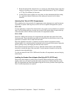
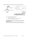
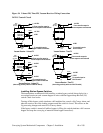
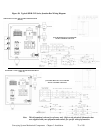
Figure 34: Volume-Fill, Time-Fill, Vacuum Receiver Wiring Connections
24 VDC Control Circuit
+24 VDC
Bin-Full switchHopper-Full/Bin-Full switches
To controller input for
0 VDC
Hopper-Full
Vacuum Receiver - Volume Fill
(LS)
switch
Bin-Full
switch (PRS)
Black
Blue
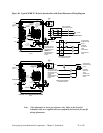
Vacuum Receiver - Time Fill
(LS)
Bin-Full
switch
0 VDC
From controller output for
vacuum sequence valve solenoid
From controller output for
+24 VDC
(SOL)
seq. valve
Vacuum
Brown
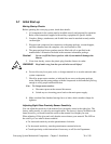
+24 VDC
(when using proximity switch as a Bin-Full switch)
Vacuum Receiver - Volume Fill
Bin-Full
switch
(LS)
Brown
Black
Blue
Brown
Blue
+24 VDC
0 VDC
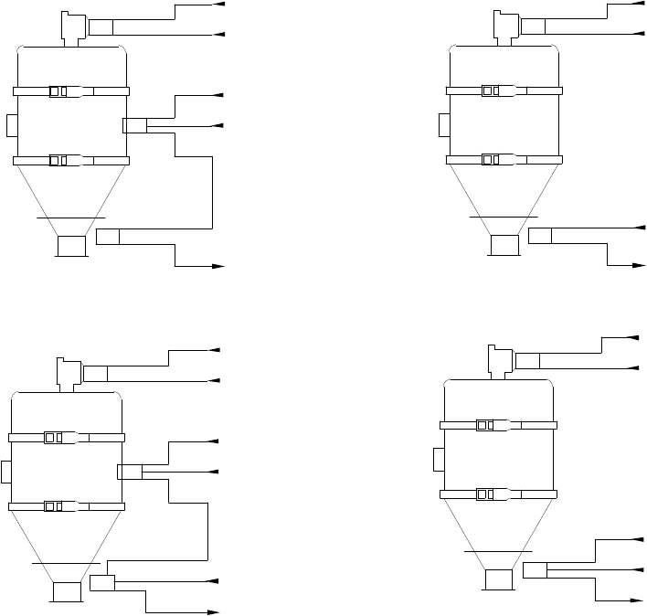
+24 VDC
+24 VDC
O VDC
+24 VDC
Bin-Full switch
Bin-Full
switch
(LS)
Blue
Black
Brown
+24 VDC
Black
vacuum sequence valve solenoid
(SOL)
seq. valve
Vacuum
To controller input for
(SOL)
seq. valve
Vacuum
(SOL)
seq. valve
Vacuum
vacuum sequence valve solenoid
From controller output for vacuum sequence valve solenoid
From controller output for
Hopper-Full/Bin-Full switches
To controller input for
Hopper-Full
switch (PRS)
Vacuum Receiver - Time Fill
(when using proximity switch as a Bin-Full switch)
To controller input for
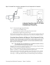
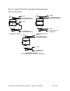
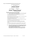
Installing Station Bypass Switches
The manufacturer recommends field-installing a station bypass switch (shown below) in a
convenient location at each vacuum hopper in series with the flapper dump Bin Full (LS)
switch. Check local codes.
Turning off this bypass switch simulates a full machine bin, cancels a No-Convey alarm, and
takes the receiver out of the loading sequence until the switch is closed. This allows on-the-
fly processing changes and cancels No-Convey alarms.
If the bypass switch is turned off while a hopper is filling, the switch simulates a full vacuum
hopper and stops the conveying of material to that hopper immediately.