


Conveying System Mechanical Components Chapter 3: Installation 53 of 138
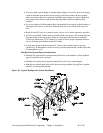
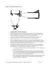
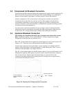
Figure 27: Typical Material Check Valve
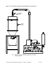
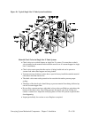
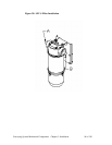
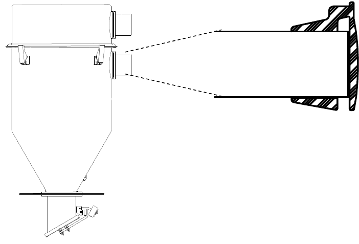
Installing SFC or FC Filter Chambers
The filter chamber protects the vacuum pump from damage caused by material carry-over.
Primary system filtration occurs in the filter chamber, not in the vacuum receivers. This
reduces maintenance of vacuum receiver filters atop processing machines.
A vortex created in the filter chamber separates carry-over from the air stream and a
cartridge-type filter catches any dust and fines drawn into the upper chamber.
At the end of the conveying cycle to all on-line vacuum receivers, the dump delay cycle
occurs. Atmospheric air from the vacuum line is introduced to the filter chamber, equalizing
the pressure inside the filter chamber. The material discharge flapper valve falls open and
dumps the fines and dust collected during the conveying cycle.
A compressed air filter cleaning blow back option is available for systems conveying very
dusty materials (See Figure 32 on page 65 for example). Consult the Sales Department for
more information. To install the unit, perform the steps listed below:
1. Level and secure the filter chamber near the pump package. Use 3/8” (9 mm) bolts to
anchor the filter chamber.
2. Connect the piping between the vacuum inlet valve on the pump package and the
tube stub on the filter chamber lid. For easy filter maintenance, install at least three
feet (3’ / 1 m) of vinyl flex hose at the end of the run to the filter chamber. The rest
may be hard piping as long as it is properly supported.
3. Run vacuum tubing from the tangential inlet tube to the vacuum header line servicing
the vacuum hoppers. Turn the inlet tube toward the header. Support the tubing
properly and make it vacuum-tight.