


Conveying System Mechanical Components Chapter 3: Installation 64 of 138
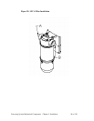
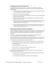
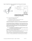
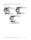
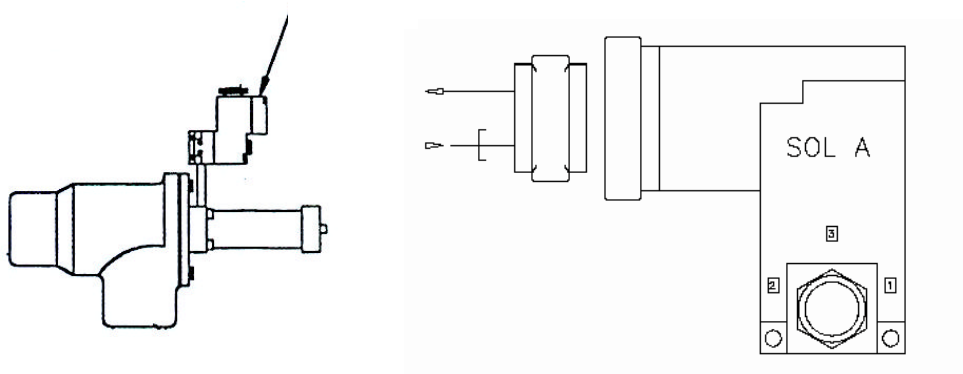
Figure 31: Solenoid Valve Location on Atmospheric Valve & Compressed Air Connections
(1) Normally Closed Port = Connect to Air Supply
(2) Common = Connect to Valve
(3) Normally Open = Exhaust Port
Your
3
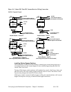
/8” (9 mm) branch supply line should include:
1. A shutoff valve for ON/OFF control.
2. An air filter/pressure regulator with a gauge for pressure control.
3. Mini-lubricators located at each vacuum receiver.
Install a quick-disconnect fitting or a shutoff valve in the compressed air piping leading to the
vacuum receiver atmospheric valve to speed receiver cover removal for cleanout or service.
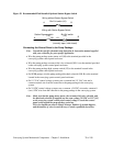
Connecting Vacuum Receivers with Sequence-T Valve Compressed Air Lines
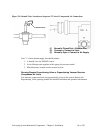
See Figure 32 on the following page for an illustration of a typical sequence-T valve. Critical
dried resin systems sometimes require sequence-T valves to prevent drawing humid atmo-
spheric air into the material supply. Sequence-T valves are usually installed in the vacuum
header above the vacuum hoppers.
Note: The sequencing valve is located in the cover on SR Series vacuum receivers if
you selected the internal sequencing valve option.
If mounted in the vacuum line, connect the sequence-T valve to a 60 psi to 80 psi (414 kPa to
552 kPa) source of clean, dry, lubricated compressed air.
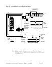
Run a
3
/8” (9 mm) branch line off the plant air main to the sequence T valves in your system.
Install a
3
/8” (9 mm) x
1
/8” (3 mm) tee in the up position near each receiver.
Connect compressed air to the normally open port on top of the sequence-T valve solenoid
valve with a
1
/8” (approx. 3 mm) pipe nipple. Connect the common port to the sequence-T
valve using
1
/4” (6 mm) poly tube and connectors. See the following for more information.
Solenoid Valve