


P/N 06160D DCN6409 Teledyne API Model 465M O
3
Monitor Instruction Manual - Page 15
4. GETTING STARTED
The M465M is shipped with the following standard equipment:
1. Power cord (Rack mount version only)
2. Instruction manual.
Upon receiving the M465M please do the following:
1. Verify that there is no apparent shipping damage. (If damage has occurred
please advise shipper first, then Teledyne API.)
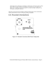
4.1. Mechanical Installation (for NEMA 4X
Enclosure)
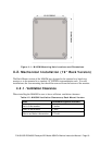
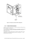
Mount the enclosure securely to a vertical surface.
Figure 4-1 shows the locations of the four mounting holes.
All four mounting holes should be used to secure the monitor.
Use stainless steel, 5/16” diameter bolts.
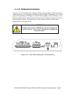
4.1.1. Ventilation Clearance
When installing the M465M be sure to leave sufficient ventilation clearance.
Table 4-1: M465M Ventilation Clearances, NEMA Version
Area Minimum required clearance
Back of the monitor None
Sides of the monitor 1 inch
Above and below the monitor 1 inch