


P/N 06160D DCN6409 Teledyne API Model 465M O
3
Monitor Instruction Manual - Page 24
The analog output is automatically scaled to the range of the instrument, i.e. if the
monitor range is 1000 PPB, then 5V would correspond to 1000 PPB and 0V would
correspond to 0 PPB. See Section 7.2.5 for information on changing the range of the
monitor.
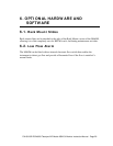
4.5.3. Status Outputs
There are four instrument status outputs located at the “General I/O” connector. These
status outputs mirror the state of the four diagnostic LED’s on the front panel. If any of
these status outputs are in a different state than shown in Table 4-3, then some adjustment
or troubleshooting should be performed. See Section 10.2 for more detailed information.
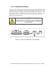
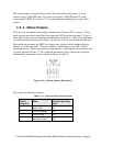
Electrically these outputs are SPST dry contact relay closures with a common contact,
labeled ‘C’ on the rear panel. They are capable of switching up to 50 VDC, 250mA
maximum current. There are no polarity requirements, so the outputs can be used to sink
or source current from the ‘C’ pin, within the maximum voltage and current specified.
Schematically, the outputs look as shown in Figure 4-8 below:
Figure 4-8: Status Output Schematic
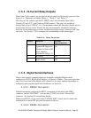
The outputs are defined as follows:
Table 4-3: Status Output Definitions
Status
Output #
Name Normal Operating
State
1 Sensor OK On
2 Invalid Reading Off
3 Check Lamp Off
4 Pneumatic Error Off