


P/N 06160D DCN6409 Teledyne API Model 465M O
3
Monitor Instruction Manual - Page 23
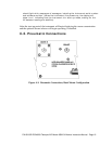
4.5. Electrical I/O Connections
4.5.1. Location of I/O Connectors in the NEMA
Configuration
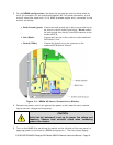
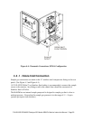
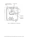
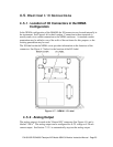
In the NEMA configuration of the M465M, the I/O connectors are located internally in
the instrument. See Figure 4-6 for their location. Connection to these terminals is
usually made via a conduit connection to the NEMA enclosure. A standard conduit
penetration may be added to one of the walls of the enclosure for this purpose, or the
existing penetration may be used.
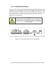
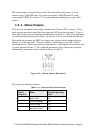
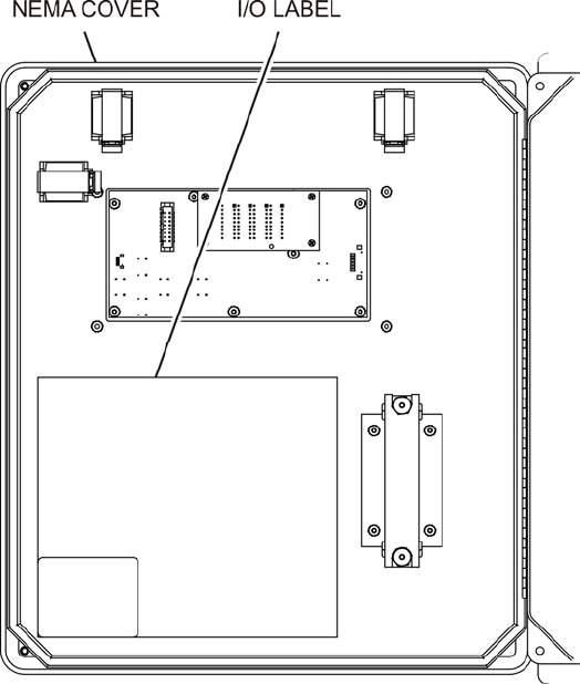
The I/O label inside the NEMA cover provides information on the functions of the
connectors. See Figure 4-7 below for the location of the I/O Label.
Figure 4-7: NEMA I/O Label
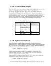
4.5.2. Analog Output
The analog output is located at the “General I/O” connector (See Figure 4-5) and is
labeled “ANA.” The analog output can be configured for 0-5V voltage or 4-20 mA
current output. See Section 7.2.3.1 to automatically step-test the analog output.