


P/N 06160D DCN6409 Teledyne API Model 465M O
3
Monitor Instruction Manual - Page 52
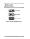
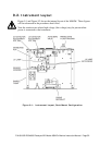
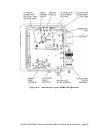
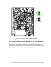
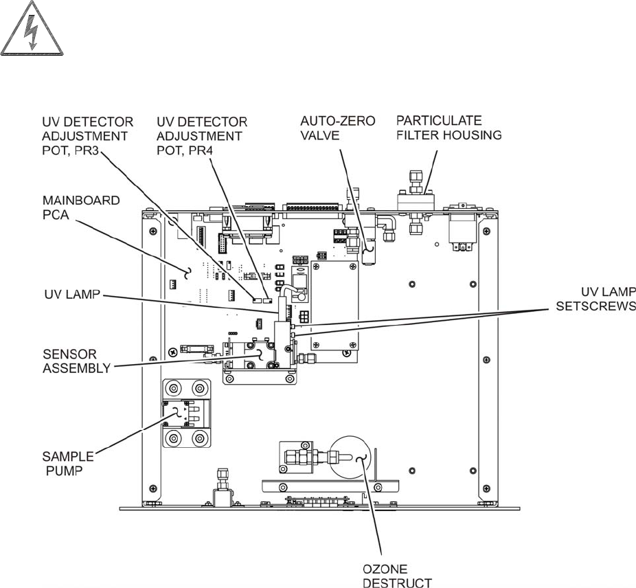
9.2. Instrument Layout
Figure 9-1 and Figure 9-2 shows the internal layout of the M465M. These figures
will be referenced in the procedures that follow.
Note the caution areas where high voltage (line voltage) may be present when
power is connected to the instrument.
Figure 9-1: Instrument Layout, Rack Mount Configuration