


P/N 06160D DCN6409 Teledyne API Model 465M O
3
Monitor Instruction Manual - Page 16
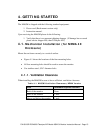
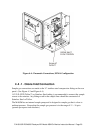
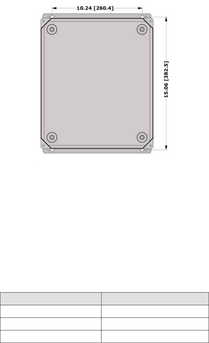
Figure 4-1: M465M Mounting Hole Locations and Dimensions
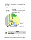
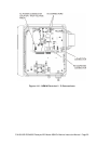
4.2. Mechanical Installation (19” Rack Version)
The Rack Mount version of the M465M was designed to be operated as a bench-top
monitor or to be mounted in a standard 19” RETMA instrumentation rack. For rack
installations, the four mounting feet should be removed from the bottom of the monitor.
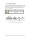
4.2.1. Ventilation Clearance
When installing the M465M be sure to leave sufficient ventilation clearance.
Table 4-2: M465M Ventilation Clearances, Rack Mount Version
Area Minimum required clearance
Back of the monitor 3 inches
Sides of the monitor 1 inch
Above and below the monitor 1/2 inch