


P/N 06160D DCN6409 Teledyne API Model 465M O
3
Monitor Instruction Manual - Page 58
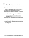
these should be removed. Use the new valve as a reference to determine which
two screws need to be removed.
8. Note the orientation of the valve body on the manifold so that the new valve can
be installed in the same orientation.
9. Remove valve body from sensor manifold.
10. Clean any residue or dirt off the surface of the manifold using a lint-free cloth and
distilled or DI water.
11. Install the new valve by reversing steps 1-7.
9.8. Configuring the Analog Output
The analog output can be configured for either 0-5V DC or 4-20mA operation. To
change or verify the configuration of the analog output:
1. Disconnect power from the M465M.
2. Remove the six screws and the top cover (Rack Mount Configuration) or open
front panel (NEMA Configuration.)
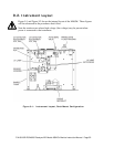
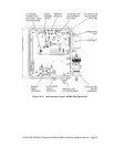
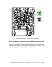
3. Locate the Mainboard PCA (see Figure 9-1 or Figure 9-2.)
4. Set the desired operation as shown in Figure 9-4.
5. Re-Install the top cover or re-secure the front panel (NEMA Configuration.)