


P/N 06160D DCN6409 Teledyne API Model 465M O
3
Monitor Instruction Manual - Page 25
4.5.4. Hi-Current Relay Outputs
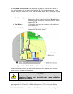
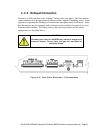
Three form C relay outputs are provided on the rear panel on the nine pin connector (See
Figure 4-5). The relays are labeled “Relay 1,” “Relay 2,” and “Relay 3.”
The relays are dry contact type form
C (SPDT) relays with Normally Open (N.O.),
Normally Closed (N.C.) and Common (COM) contacts. The relays are capable of
driving loads of up to 250VAC, 5A. For maximum contact life, the relays should only be
used to drive resistive loads. Contact life may be dramatically shortened if inductive
loads are driven without any provision for minimizing high voltage “inductive kick” that
can occur. See Section 7.2.6 to configure the concentration for the alarm trigger.
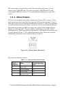
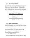
Table 4-4: Relay Functions
Relay # Function Normal
Operating State
1 System OK Diagnostic
(Identical to Sensor OK
status output as
described in Table 4-3)
On
2 Hi Alarm Off
3 Hi-Hi Alarm Off
4.5.5. Digital Serial Interfaces
There is one external communications port available on the M465M that can be
configured as RS232, RS485 (Half Duplex,) or Ethernet (10Mbit.) This section provides
only a brief overview of the digital serial connections, for more detailed information on
configuring and using the digital serial interfaces, see Section 8.
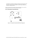
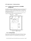
4.5.5.1. RS232 Connection
With the instrument configured for RS232, connection can be made to the DB-9
connector, labeled “RS232/485”, or to the three “COM” pins on the “General I/O”
connector. See Section 8.2 for additional details.
W
hen using RS232, a 9-pin serial cable (TAPI P/N WR77) can be used to connect the
instrument to a standard PC (personal computer) serial port.
4.5.5.2. RS485 Connection