


P/N 06160D DCN6409 Teledyne API Model 465M O
3
Monitor Instruction Manual - Page 63
10. TROUBLESHOOTING
10.1. Reference Drawings
The drawings contained in this section are for general reference and may be useful when
performing certain troubleshooting activities.
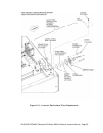
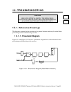
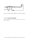
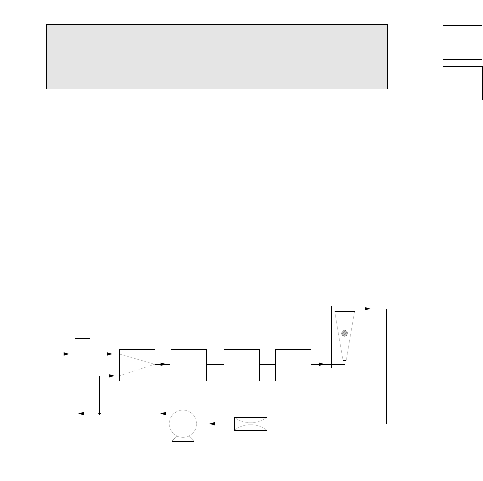
10.1.1. Pneumatic Diagram
Figure 10-1 and Figure 10-2 below is a pneumatic diagram that can be referenced when
performing troubleshooting on the monitor.
Exhaust Out
O3 Gas In
Azero Valve
Filter
O3
Measurement
Cell
O3 Destruct
Flow-Meter
Pump
Flow Control
Orifice
Flow Switch
(Optional)
Figure 10-1: Pneumatic Diagram (Rack Mount Version)
CAUTION
RISK OF ELECTRICAL SHOCK. THE OPERATIONS
OUTLINED IN THIS CHAPTER ARE TO BE PERFORMED BY
QUALIFIED MAINTENANCE PERSONNEL ONLY!