6 WSHP-PRC001-EN
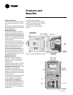
Hanging Device
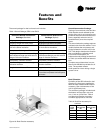
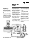
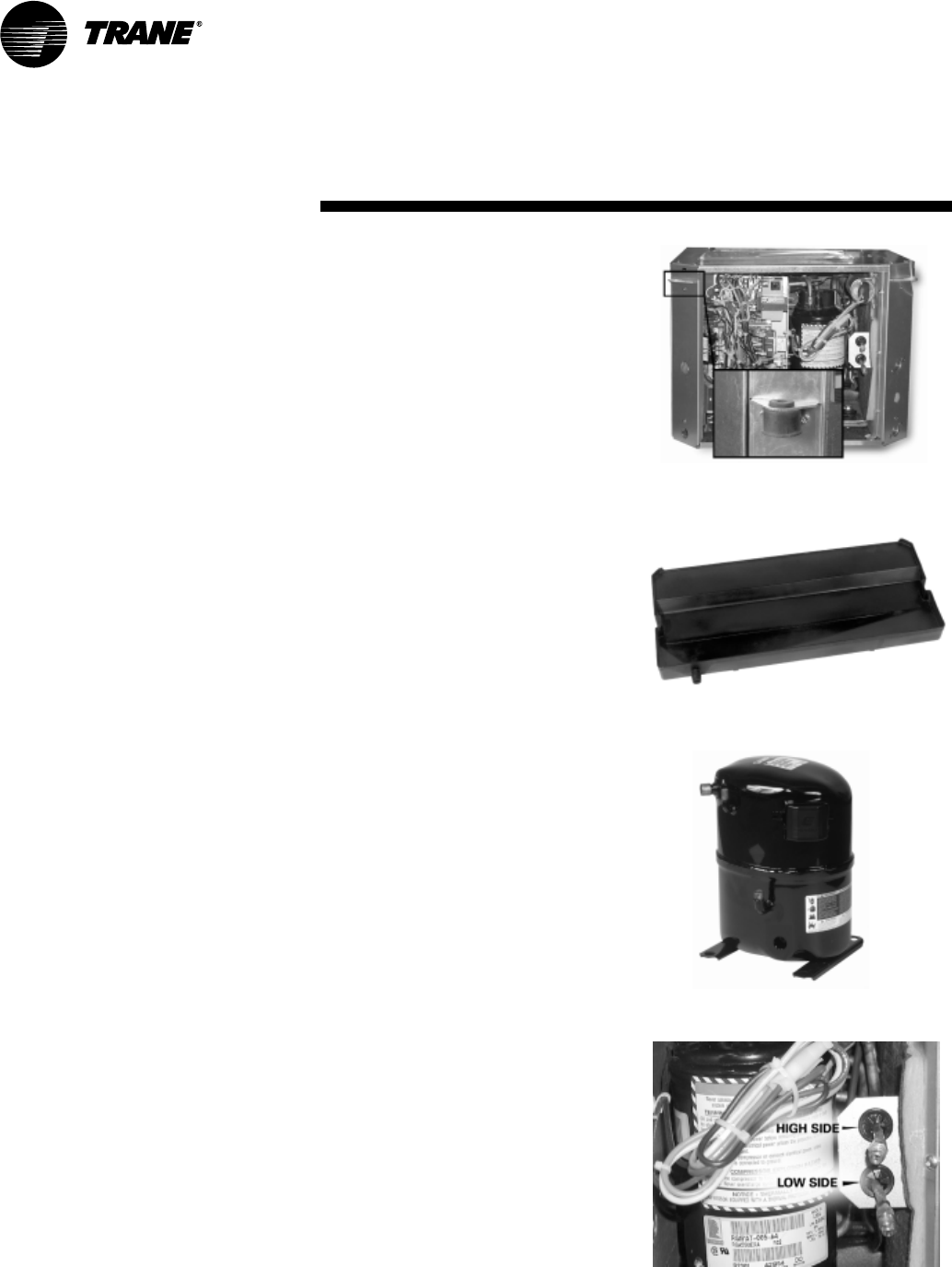
The hanging bracket resides in the
chamfered corner of the horizontal 1/2
to 5 ton equipment. This partially-con-
cealed bracket design eliminates add-
ed height, width, or length to the
product. The brackets are factory
mounted to shorten job installation re-
quirements.
The structural integrity of the design
helps assure no bracket deflection or
unit bowing from the unit’s weight.
Field return-air hook-up and filter
maintenance are more simplistic. Iso-
lation for the hanging bracket is pro-
vided with a neoprene rubber
grommet design. This isolation device
helps prevent sound vibration from
reaching the structural support mem-
bers of the building during compres-
sor start and stop. See Figure 5 for
isolation device.
Drain Pan
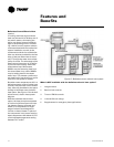
The unit drain pan is composed of
plastic, corrosive resistive material.
The pan is positively sloped to comply
with ASHRAE 62 for (IAQ) indoor air
quality conformity.
Access to the drain pan is provided
through two access panels for clean-
ing purposes. See Figure 6 for plastic
drain pan.
Cabinet Insulation
The cabinet insulation design meets
UL 181 requirements. The air stream
surface of the insulation is fabricated
of a non-biodegradable source.
Refrigeration Piping
The unit’s copper tubing is created
from a 99% pure copper formation that
conforms to the American Society of
Testing (ASTM) B743 for seamless,
light-annealed processing.
The unit’s copper refrigeration system
is designed to be free from contami-
nants and conditions such as drilling
fragments, dirt, or oil. This excludes
the possibility of these contaminants
from damaging the compressor mo-
tor.
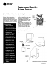
Compressor
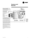
The unit’s design includes a wide vari-
ety of compressor motors to accom-
modate dedicated voltages and
tonnage sizes. The 1/2 ton through
1 1/2 ton products embody a rotary
compressor design, where as unit siz-
es ranging from 2 ton through 4 ton in-
clude a reciprocating compressor
style, while the 5 ton unit contains a
scroll compressor. These different
styles allow Trane to provide the volt-
age variations along with noise reduc-
tion required in today’s applications.
See Figure 7 for reciprocating com-
pressor.
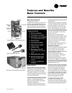
Schrader Connections
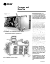
The connections for the low and high
side of the refrigeration system are lo-
cated directly beside the control box at
the front, service access panel. See
Figure 8 for schrader connection lo-
tion.
Features and
Benefits
Figure 5: Hanging bracket design
Figure 6: Plastic drain pan
Figure 7: Reciprocating compressor
Figure 8: Schrader connections


