8 WSHP-PRC001-EN
Blower Motor
The supply-air (blower) motor is a
multi-speed motor with internal ther-
mal overload protection. The motor
bearings are permanently lubricated
and sealed. Standard motors are rated
from .20 ESP. Optional high static mo-
tors are rated from .40 to 1.40 ESP. All
motors are factory wired to the option
selected. A high, medium, and low
speed tap is provided for field custom-
ization on most voltages. The speed
tap modification can be made in the
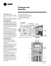
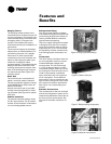
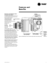
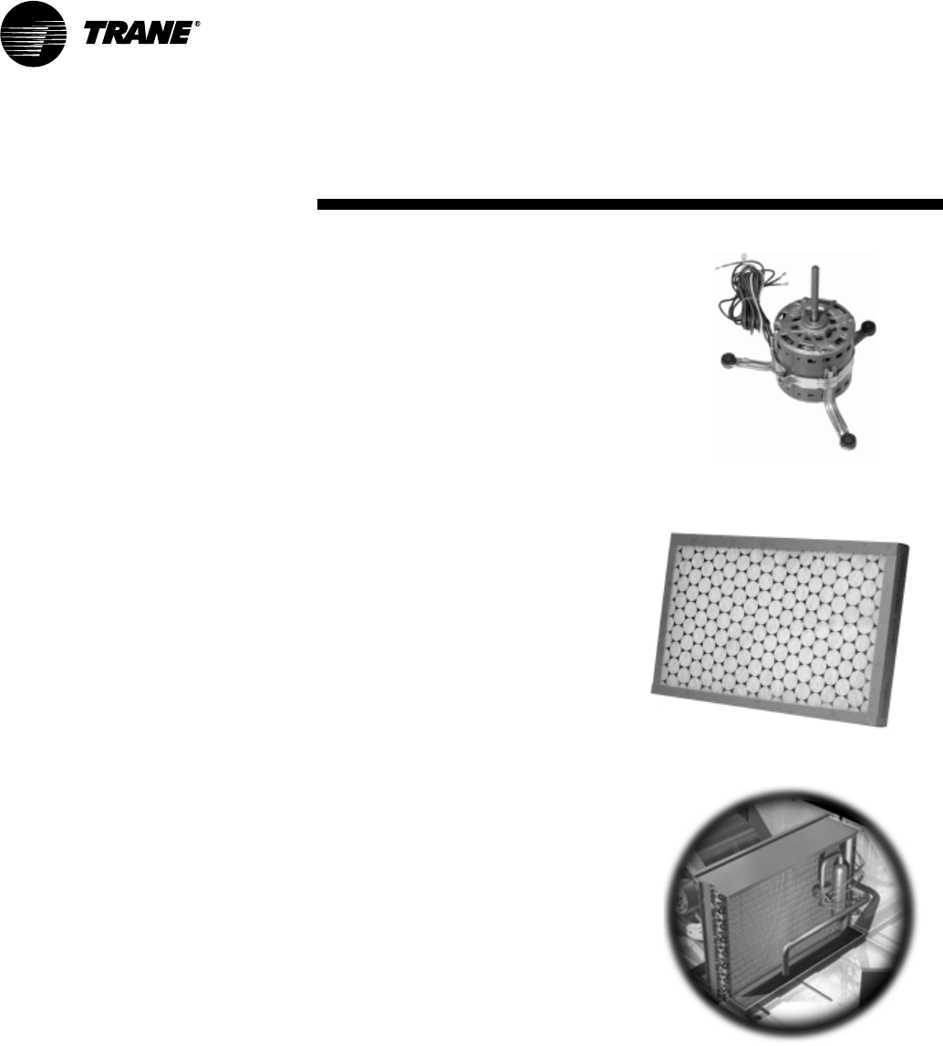
control box of the unit. See Figure 13
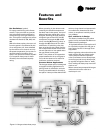
for blower motor.
Note: The 380, 415, 460 and 575 volt
designs are provided in a dual or
three-speed version only. See fan per-
formance section for factory ratings
(Page 66).
Serviceability to the motor is made
through either of the two air-side ac-
cess doors for the horizontal configu-
ration, and through one air-side
access door on vertical configuration.
The motor and blower wheel are re-
movable by an orifice ring mounted to
the fan housing.
Blower Housing
The blower housing is constructed of
non-corrosive galvanized steel. A fac-
tory-mounted orifice ring is provided
for ease of motor serviceability on the
1/2 through 5-ton direct drive units.
All air-side panels are interchangeable
with one another for ease of field con-
vertibility of the supply-air on the GEH
model.
Air-Side Filter
The air-side filter incorporates a 1-inch
thick (nominal) or 2-inch thick (nomi-
nal) disposable fiberglass option.
These filters include an average syn-
thetic dust weight arrestance of ap-
proximately 75%. This dust holding
capability includes a colorless, odor-
less adhesive to retain dirt particles
within the filter media after fiber con-
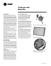
tact. See Figure 14 for filter media.
Air-to-Refrigerant Coil
The air-to-refrigerant heat exchanger
is constructed of staggered copper
tubes with die-formed corrugated
lanced aluminum fins. The fins are
then mechanically bonded to the
tubes through expansion.
The coil is placed internal of the unit
design for the GEH model to provides
an optional dual filtration application.
With dual filtration to the GEH unit,
maintenance to the filter is significant-
ly less than with a single filtration sys-
tem. This design also offers maximum
flexiblity of the supply and return air
configurations.
The maximum working pressure for
both the GEH and GEV coils is 450
psig. It is designed for maximum ca-
pacity with an additional benefit of
physical unit size reduction.
Coil specifications for both GEH and
GEV models may be found on in the
General Data section on page 36 of
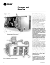
this catalog. See Figure 15 for internal
air to refrigerant coil placement.
Features and
Benefits
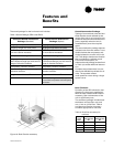
Figure 13: Blower motor (direct drive)
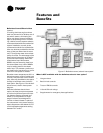
Figure 14: Filter media
Figure 15: Internal air-to-refrigerant
coil placement (model GEH)


