


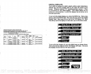
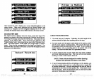

Press the
key adjacent
to the desired
speed
label. For
example,
it
you
wish
to
display
the
speed
in
knots,
press
the
key adjacent
to the
"Speed
in knots" The Z-9500 reverts to the sonar
display
after the
key
is
pressed.
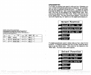
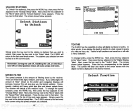
SPEEDOMETER CALIBRATION
The
speedometer
display
can be calibrated to
accurately
show the
boat's
speed.
Calibrate the
reading using
the
Speedometer
Calibration
menu.
To use this
menu,
first
press
the MENU
key.
Next,
press
the
key adjacent
to the MORE label. Now
press
the
key adjacent
to the
"Digital Display"
label, Press the
key
next to the "More" label. Then
press
the
key
next to the
"Speed"
label.
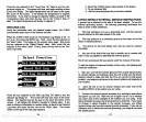
Finally, press
the
key adjacent
to the "Calibrate
Speed"
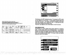
label. The screen shown below
appears.
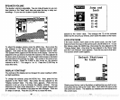
The
current boat
speed
is
displayed
on the
right
side of the screen. To
increase the
displayed speed, press
the
key adjacent
to the
up
arrow
on the
"Speed"
menu. To decrease
it,
press
the
key adjacent
to the
down
arrow. As the
displayed speed changes,
the amount of the
change
in
percent
also
displays immediately
below it. For
example,
if
you
are
traveling
at ten miles
per
hour,
pressing
the
key adjacent
to the
down arrow once will decrease the
displayed speed by
-1
%,
or 1 mile
per
hour. The
displayed speed
would then be 9 miles
per
hour.
The best
way
to calibrate the
speedometer
is to have someone else
drive the boat
through
a measured mile at a constant
speed.
Time how
long
it takes to travel the
mile,
then calculate
your
actual
speed using
this formula:
60/Time=Speed.
Now make the run
through
the mile
in
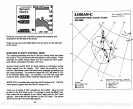
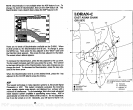
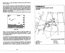
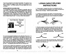
LORAN CABLE
SPLICING
INSTRUCTIONS
1. Cut the cable
in
a location
that will be in a
protected
area in the
boat. The
splice
shouldn't
be
exposed
to rain or
spray,
nor should ft be
allowed to
lay
in the
bilge.
Route the cable as desired.
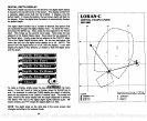
2.
Carefully
cut and
strip
the outer
jacket
1"
from the
end of each
cable.
Unwrap
the shield from the four wires. Remove the shield,
as it
isn't needed. You should have four wires
remaining;
three insulated
and one uninsulated.
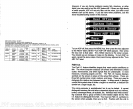
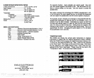
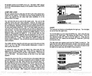
3.
Strip
the insulation from
the wires about 3/8" from the end. Twist
one wire from each cable
together,
making
sure that
you
match the
colors of the wires.
Damage
can occur to the loran module or the
display
unit if
you
wire the cable
incorrectly.
Solder the
connection,
then
wrap
it with a
good quality
electrical
tape.
Do the same for the
other three wires.
SOLDER
TAPE
4.
Finally, wrap
the entire
splice
with electrical
tape. Wrap
the cables
together
at the same
time. This creates a strain relief for the
splice.
The loran is now
ready
for use.
32
105
Speed
Clear
-
PDF compression, OCR, web-optimization with CVISION's PdfCompressor