


LF-Series Flowmeters: Sensor/Transmitter Installation 11
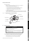
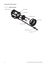
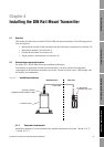
Installing the Field-Mount Transmitter
Installing the Sensor Installing the DIN TransmitterInstalling the FM TransmitterBefore You Begin
DC power requirements
Note: These requirements assume a single transmitter per cable. Connecting multiple transmitters to
a single cable should generally be avoided.
If you are using DC power, the following requirements apply:
• 18–100 VDC
• 6 watts typical, 11 watts maximum
• At startup, the transmitter power source must provide a minimum of 1.5 amps of short-term
current per transmitter.
• Length and conductor diameter of the power cable must be sized to provide 18 VDC minimum
at the power terminals, at a load current of 0.5 amps. To size the cable, refer to Table 3-1 and
use the following formula as a guideline:
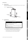
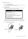
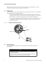
3.2.4 Distance from sensor
The maximum cable length between the sensor and the transmitter is 1000 ft (300 m).
Micro Motion supplies 4-wire cable to connect the sensor to the transmitter. The cable is fitted with a
Eurofast connector for connection to the sensor. Cable can be ordered in lengths ranging from 6.5 ft
(2 m) to 500 ft (150 m). For longer cable lengths, contact the factory.
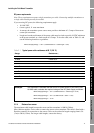
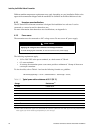
Table 3-1 Typical power cable resistances at 68 °F (20 °C)
Gauge Resistance
(1)
(1) These values include the resistance of both high and low conductors in a cable.
14 AWG 0.0050 Ω/foot
16 AWG 0.0080 Ω/foot
18 AWG 0.0128 Ω/foot
20 AWG 0.0204 Ω/foot
2,5 mm
2
0,0136 Ω/meter
1,5 mm
2
0,0228 Ω/meter
1 mm
2
0,0340 Ω/meter
0,75 mm
2
0,0460 Ω/meter
0,5 mm
2
0,0680 Ω/meter
Example
The transmitter is mounted 350 feet from a DC power supply. If you want to use
16 AWG cable, calculate the required voltage at the DC power supply as follows:
MinimumSupplyVoltage 18V CableResistance CableLength× 0.5A×()+=
MinimumSupplyVoltage 18V 0.0080 ohms/ft 350 ft× 0.5A×()+=
MinimumSupplyVoltage 19.4V=
MinimumSupplyVoltage 18V CableResistance CableLength× 0.5A×()+=