


54 LF-Series Flowmeters: Sensor/Transmitter Installation
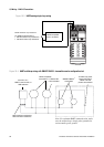
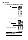
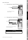
I/O Wiring – DIN CIO Transmitters
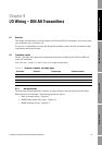
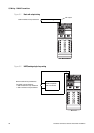
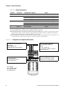
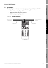
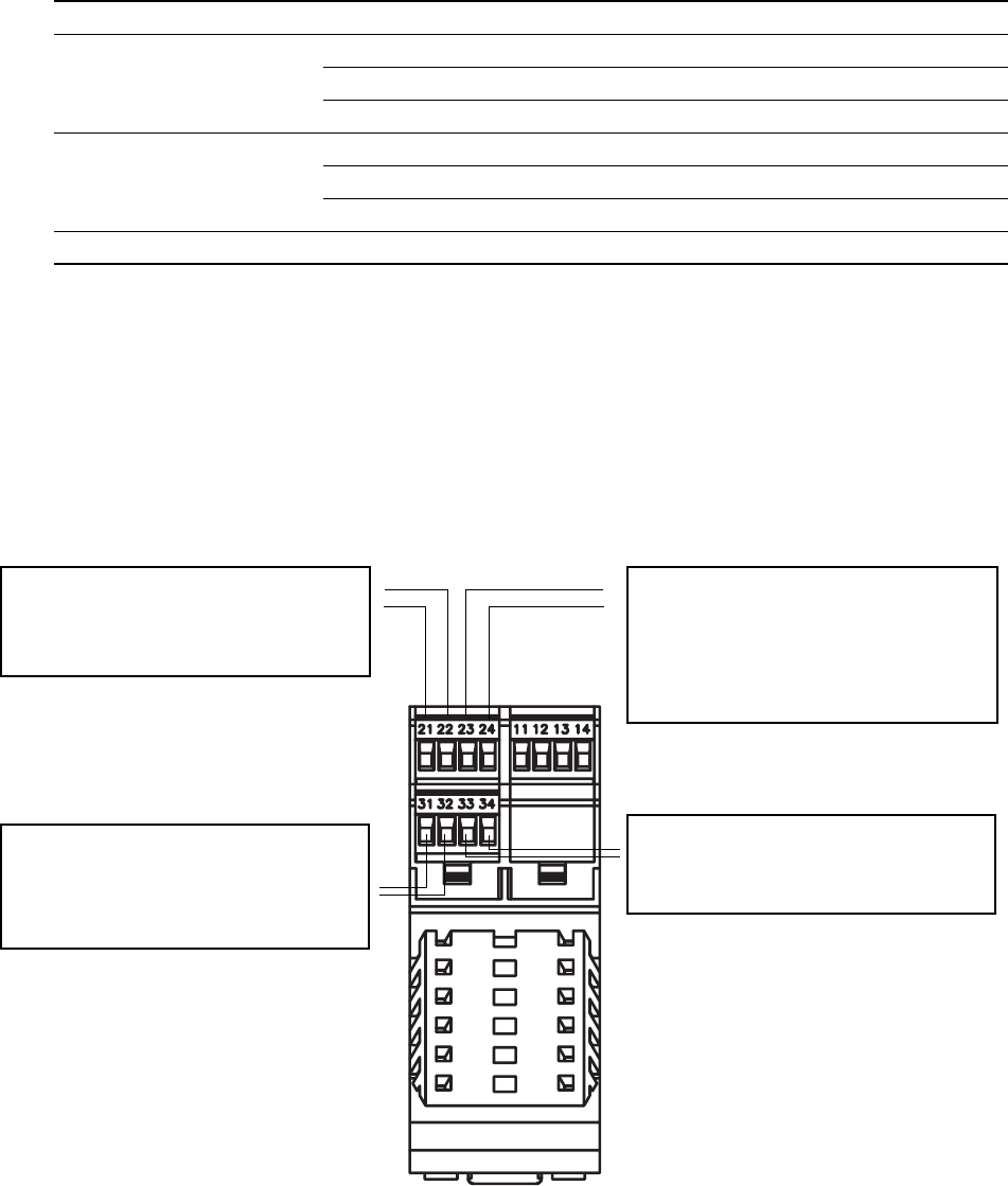
Figure 10-1 Configuration of configurable I/O terminals
Table 10-1 Channel configuration
Channel Terminals Configuration options Power
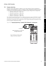
A 21 & 22 mA output with HART/Bell 202
(1)
(1) The Bell 202 signal is superimposed on the mA output.
Internal
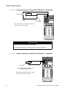
B 23 & 24 • mA output (default) Internal
• Frequency output
(2)
(2) Can be configured for active high or active low polarity. Default is active high.
Internal or external
(3)
(3) You must provide power to the outputs when a channel is set to external power.
• Discrete output
(4)
(4) Because discrete output 1 uses the same circuitry as the frequency output, it is not possible to configure both a frequency
ouput and discrete output 1. If both a frequency output and a discrete output are required, configure Channel B as the
frequency output and Channel C as the discrete output (discrete output 2).
Internal or external
(3)
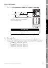
C 31 & 32 • Frequency output (default)
(5)
(5) When configured for two frequency outputs (dual pulse), frequency output 2 is generated from the same signal that is sent
to the first frequency output. Frequency output 2 is electrically isolated but not independent.
Internal or external
(3)
• Discrete output Internal or external
(3)
• Discrete input Internal or external
(3)
D 33 & 34 Modbus/RS-485 Internal
Terminals 21 & 22 (Channel A)
mA1 output
Internal power only
HART (Bell 202) communications
Terminals 23 & 24 (Channel B)
mA2 output OR FO OR DO1
Power:
• mA – internal only
• FO or DO1 – internal or external
No communications
Terminals 31 & 32 (Channel C)
FO OR DO2 OR DI
Power: internal or external
No communications
mA = milliamp
FO = frequency output
DO = discrete output
DI = discrete input
Terminals 33 & 34
Service port OR Modbus RS-485
(Modbus RTU or Modbus ASCII)