


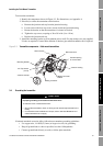
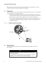


18 LF-Series Flowmeters: Sensor/Transmitter Installation
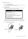
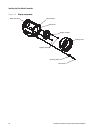
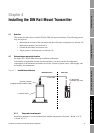
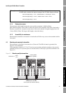
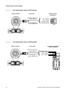
Installing the DIN Rail Mount Transmitter
Different ambient temperature requirements may apply, depending on your installation. Refer to the
approvals documentation shipped with the transmitter or available on the Micro Motion web site.
4.2.2 Hazardous area classifications
The LF-Series DIN rail mount transmitter is designed for installation in a safe area. It can be
connected to a sensor located in a hazardous area.
For more information about hazardous area classifications, see Appendix A.
4.2.3 Power source
The transmitter must be connected to a DC voltage source. Do not use an AC power supply.
The following requirements apply:
• 19.2 to 28.8 VDC at the power terminals, at a load current of 330 mA
• 6.3 watts maximum
• At startup, the transmitter power source must provide a minimum of 1.0 amp of short-term
current per transmitter
To size the cable, refer to Table 4-1 and use the following formula as a guideline:
CAUTION
Applying AC voltage to the transmitter will damage the device.
To avoid damaging the transmitter, do not connect it to an AC power supply.
Table 4-1 Typical power cable resistances at 68 °F (20 °C)
Gauge Resistance
(1)
(1) These values are based on copper wire, and include the resistance of both wires in a cable. If you are using a material other
than copper, refer to the resistivity specifications for your wire type.
14 AWG 0.0050 Ω/foot
16 AWG 0.0080 Ω/foot
18 AWG 0.0128 Ω/foot
20 AWG 0.0204 Ω/foot
2,5 mm
2
0,0136 Ω/meter
1,5 mm
2
0,0228 Ω/meter
1 mm
2
0,0340 Ω/meter
0,75 mm
2
0,0460 Ω/meter
0,5 mm
2
0,0680 Ω/meter
MinimumSupplyVoltage 19.2V CableResistance CableLength× 0.33 A×()+=