


LF-Series Flowmeters: Sensor/Transmitter Installation 59
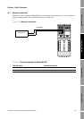
I/O Wiring – DIN CIO Transmitters
I/O Wiring – DIN CIO Return PolicySpecificationsI/O Wiring – DIN AN
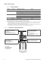
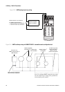
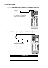
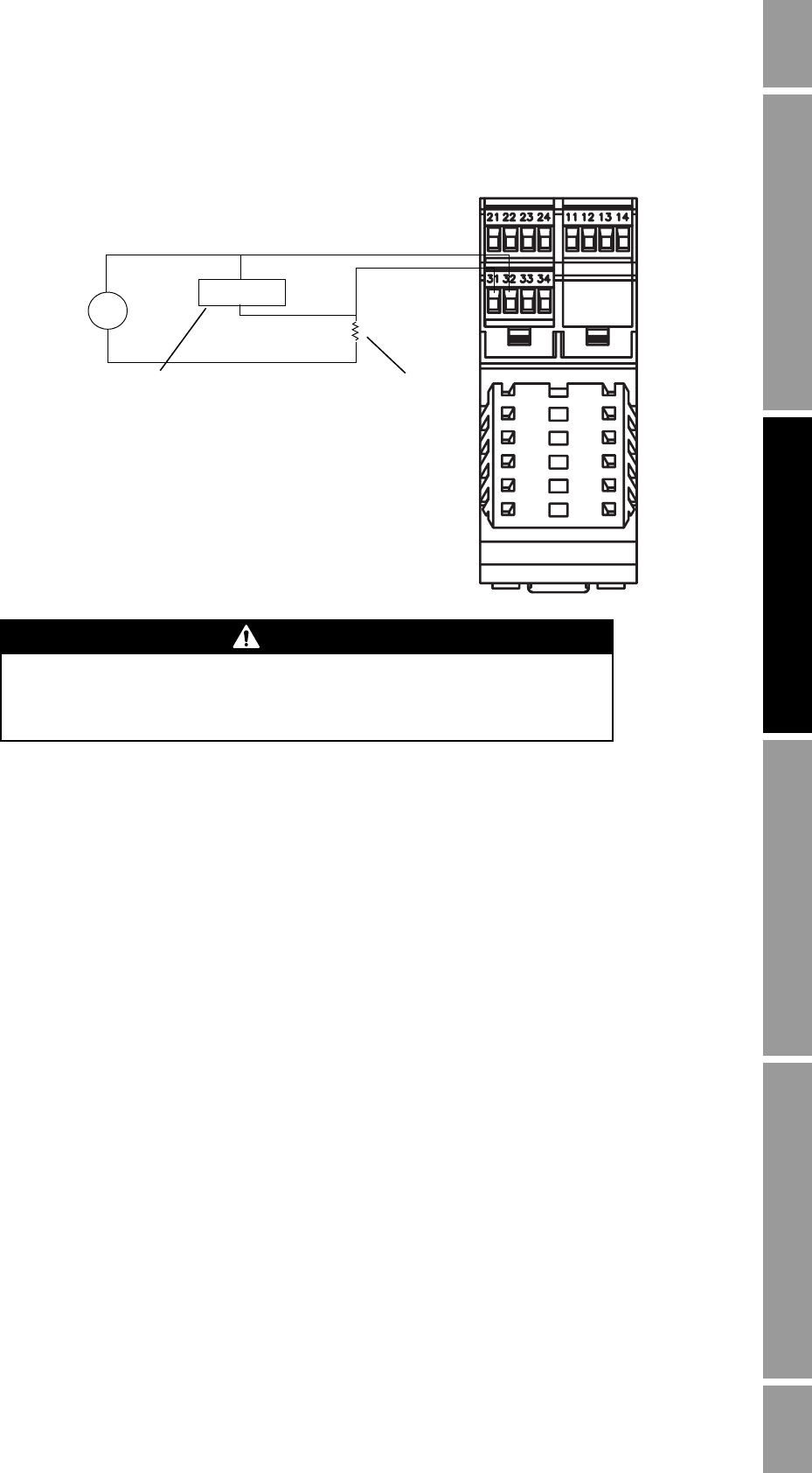
Figure 10-8 Frequency output wiring – Terminals 31 & 32 (Channel C) – External power
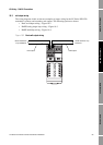
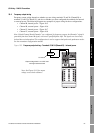
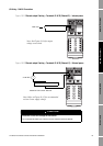
10.5 Discrete output wiring
Discrete output wiring depends on whether you are wiring terminals 23 and 24 (Channel B) or
terminals 31 and 32 (Channel C), and also on whether you have configured the terminals for internal
or external power. The following diagrams are examples of proper wiring for these configurations:
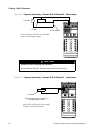
• Channel B (DO1), internal power – Figure 10-9
• Channel B (DO1), external power – Figure 10-10
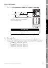
• Channel C (DO2), internal power – Figure 10-11
• Channel C (DO2), external power – Figure 10-12
3–30 VDC
Pull-up resistor
Counter
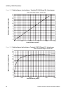
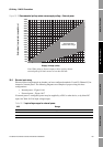
Note: Refer to Figure 10-15 for recommended
resistor versus supply voltage.
000042
–
+
+
–
CAUTION
Excessive current will damage the transmitter.
Do not exceed 30 VDC input. Terminal current must be less than 500 mA.