


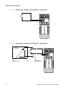
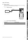


72 LF-Series Flowmeters: Sensor/Transmitter Installation
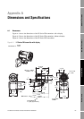
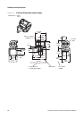
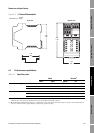
Dimensions and Specifications
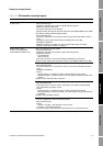
A.3.2 LF-Series FM transmitters
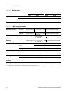
Table A-8 Output options for transmitters with configurable I/O
Channel
Terminals
Configuration option
Default process
variable assignment PowerFM DIN
A 1 & 2 21 & 22 mA output 1
(with Bell 202 HART)
Mass flow Internal (active)
B 3 & 4 23 & 24 mA output 2 (default) Density Internal (active)
Frequency output (FO)
(1)
(1) When configured for two FOs (dual pulse), FO2 is generated from the same FO signal sent to the first FO. FO2 is electrically
isolated but not independent.
Mass flow Internal (active) or
external (passive)
Discrete output 1 (DO1) Fwd/Rev
C 5 & 6 31 & 32 FO (default)
(1)
Mass flow Internal (active) or
external (passive)
Discrete output 2 (DO2) Flow switch
Discrete input (DI) None
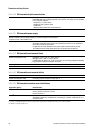
Table A-9 FM transmitter physical specifications
Weight With display: 8 lb (3, 6 kg)
Without display: 7 lb (3,2 kg)
Mounting and cabling Transmitters include a mounting bracket and 6.5 ft (2 m) of 4-wire twisted-pair
shielded signal cable. Additional lengths up to 1000 ft (300 m) can be purchased.
Hardware for installing the transmitter on the mounting bracket is included.
The transmitter can be rotated on the mounting bracket, 360° in 90° increments.
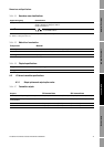
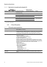
Interface/Display (optional) Segmented 2-line display with LCD screen with optical controls and flowmeter-
status LED is standard.
• LCD line 1 lists the process variable.
• LCD line 2 lists engineering unit of measure.
Non-glare tempered glass lens.
Available in both backlit and non-backlit versions.
Display is suitable for hazardous area installation. To facilitate various mounting
orientations, the display can be rotated on the transmitter, 360° in 90° increments.
Display controls feature optical switches that are operated through the glass with a
red LED for visual feedback to confirm when a “button” is pressed.
Display functions:
• View process variables
• Start, stop and reset totalizers
• View and acknowledge alarms
• Off-line (where applicable):
• Zero flowmeter
• Simulate outputs
• Change measurement units
• Configure ouputs
• Set RS-485 communications options
Status light Three-color LED status light on display panel indicates flowmeter condition at a
glance.