


LF-Series Flowmeters: Sensor/Transmitter Installation 47
I/O Wiring – DIN CIO Return PolicySpecificationsI/O Wiring – DIN AN
Chapter 9
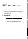
I/O Wiring – DIN AN Transmitters
9.1 Overview
This chapter describes how to wire the outputs for LF-Series DIN AN transmitters. If you don’t know
your transmitter type, see Section 1.6.
It is the user’s responsibility to verify that the specific installation meets the local and national safety
requirements and electrical codes.
9.2 Transmitter outputs
Table 9-1 describes the outputs and communication protocols available for the LF-Series DIN rail
mount AN transmitter.
Note: The term “channel” is used to refer to the output terminal pairs.
9.2.1 mA output wiring
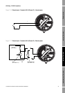
The following wiring diagrams are examples of proper wiring for the mA output on the LF-Series
DIN rail mount AN transmitter. The following options are shown:
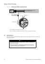
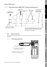
• Basic mA output wiring – Figure 9-1
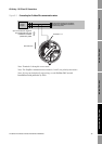
• HART/analog single-loop wiring – Figure 9-2
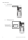
• HART multidrop wiring – Figure 9-3
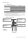
Table 9-1 Terminals, channels, and output types
Terminals Channel Output type Communication
21 & 22 A Milliamp HART/Bell202
23 & 24 B Not used None
31 & 32 C Frequency None
33 & 34 N/A Digital Modbus/RS-485