


74 LF-Series Flowmeters: Sensor/Transmitter Installation
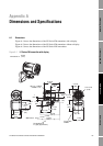
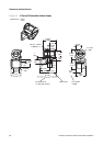
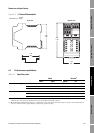
Dimensions and Specifications
Output option code 4
(2 mA, 1 FO configurable,
multivariable transmitter only)
One or two active 4–20 mA outputs
• Not intrinsically safe
• Isolated to ±50 VDC from all other outputs and earth ground
• Maximum load limit:
- mA1: 820 ohms
- mA2: 420 ohms
• Can report mass flow, volume flow, density, temperature, or drive gain
• Output is linear with process from 3.8 to 20.5 mA, per NAMUR NE43 (June 1994)
One active or passive frequency/pulse output
• Not intrinsically safe
• Can report mass flow or volume flow, which can be used to indicate flow rate or
total
• Scalable to 10,000 Hz
•Power:
- Internal (active): +15 VDC ±3% with a 2.2 kohm internal pull-up resistor
- External (passive): +30 VDC maximum, +24 VDC typical
• Output is linear with flow rate to 12,500 Hz
One or two active or passive discrete outputs
• Not intrinsically safe
• Can report event 1, event 2, event 1 and event 2, flow switch, forward/reverse
flow, calibration in progress, or fault
•Power:
- Internal (active): +15 VDC ±3% with a 2.2 kohm internal pull-up resistor
- External (passive): +30 VDC maximum, +24 VDC typical
• Maximum sink capability: 500 mA
One discrete input
• Can be configured for internal or external power
• Not intrinsically safe
•Power:
- Internal (active): +15 VDC, 7 mA maximum source current
- External (passive): +3 to 30 VDC maximum
• Can report reset all totals, reset mass total, reset volume total, or start sensor
zero
Output option code 6
(F
OUNDATION fieldbus)
One F
OUNDATION fieldbus H1 output
Manchester-encoded digital signal conforms to IEC 1158-2
Output option code 7
(Profibus-PA)
One Profibus-PA output
Manchester-encoded digital signal conforms to IEC 1158-2
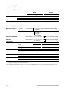
Table A-12 FM transmitter digital communications
All transmitters One service port can be used for temporary connection only
Uses RS-485 Modbus signal, 38.4 kilobaud, one stop bit, no parity
Output option code 1, 3, or 4 HART Bell 202 signal is superimposed on the primary milliamp output, and is
available for host system interface:
• Frequency: 1.2 and 2.2 kHz
• Amplitude: to 0.8 V peak-to-peak
• 1200 baud
• Requires 250 to 600 ohms resistance
Output option code 1 or 3 One RS-485 output can be used for direct connection to a HART or Modbus host
system.
Modbus communications supports 7-bit or 8-bit protocol (default: 8-bit), 1200 to
38,400 baud (default: 9600), one or two stop bits (default: one), and odd, even, or
no parity (default: odd). Configuration can be changed using ProLink II software or
the display (if applicable).
Table A-11 FM transmitter input/output signals continued