


26 LF-Series Flowmeters: Sensor/Transmitter Installation
Wiring the Sensor to the Transmitter
5.4.2 Wiring
To connect the cable, follow the steps below.
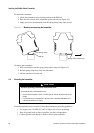
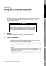
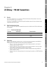
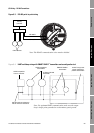
1. To connect the cable to the sensor, plug the Eurofast connector onto the top of the sensor
connection. The connector is keyed for appropriate orientation.
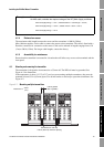
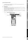
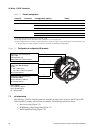
2. At the remote host:
a. Open the wiring compartment and identify the RS-485 terminals. Refer to the vendor
documentation if required.
b. Connect the RS-485 wires from the sensor to the RS-485 terminals at the remote host. The
blue wire is RS-485/A; the white wire is RS-485/B.
c. Do not terminate the shield, braid, or drain wire(s) at the remote host.
d. Do not terminate the RS-485 lines using the standard 60-ohm termination resistor. If
possible, do not terminate the RS-485 lines at all. If the RS-485 cable is 1000 feet (300
meters) long or longer, and termination is required, the total termination must be 175 ohm
or above.
e. Close the wiring compartment.
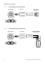
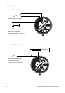
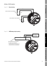
3. At the power supply, connect the power supply wires from the sensor to the power supply,
matching positive and negative (+ and –). The brown wire is VDC+; the black wire is VDC–.
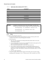
Table 5-1 Typical power cable resistances at 68 °F (20 °C)
Gauge Resistance
(1)
(1) These values include the resistance of both high and low conductors in a cable.
14 AWG 0.0050 Ω/foot
16 AWG 0.0080 Ω/foot
18 AWG 0.0128 Ω/foot
20 AWG 0.0204 Ω/foot
22 AWG 0.0328 Ω/foot
2,5 mm
2
0,0136 Ω/meter
1,5 mm
2
0,0228 Ω/meter
1 mm
2
0,0340 Ω/meter
0,75 mm
2
0,0460 Ω/meter
0,5 mm
2
0,0680 Ω/meter
Example
The sensor is mounted 350 feet from a DC power supply. If you want to use
18 AWG cable, calculate the required voltage at the DC power supply as follows:
MinimumSupplyVoltage 15V 0.0128 ohms/ft 350 ft× 0.15A×()+=
MinimumSupplyVoltage 15V CableResistance CableLength× 0.15A×()+=
MinimumSupplyVoltage 15.7V=