


LF-Series Flowmeters: Sensor/Transmitter Installation 25
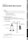
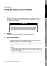
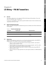
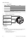
Wiring the Sensor to the Transmitter
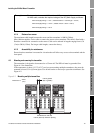
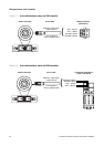
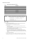
I/O Wiring – FM AN I/O Wiring – FM FB and PAI/O Wiring – FM CIOSensor Wiring
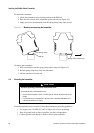
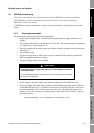
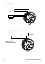
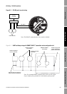
5.4 MVD Direct Connect wiring
Note: This section applies only to LF-Series sensors used in MVD Direct Connect installations.
Note: MVD Direct Connect installations based on the LF-Series sensor cannot include the
MVD Direct Connect I.S. barrier.
In MVD Direct Connect installations, you must connect the sensor to a remote host and to a power
supply.
5.4.1 Power supply requirements
The power supply must meet the following requirements:
• Power must be supplied from a common floating regulated power supply with the correct
voltage.
• The voltage requirement for a single sensor is 15–26 VDC. The maximum power consumption
of a single sensor is approximately 3 W.
• The power supply may be used to power any number of sensors, but must not be used to power
other devices.
• Use shielded wiring.
• The power supply must not allow power surges or conducted radio frequency interference
(RFI) to propagate through to its output.
• The power supply must not be grounded.
• In EU countries, the power supply must meet the requirements of the EMC directive.
• The power supply cable must comply with the size and length requirements listed in Table 2-1.
A minimum DC input of 15 V is required for each sensor. At startup, the power source must
provide a minimum of 0.2 A of short-term current per sensor. The maximum steady state
current is 0.15 A. For assistance in sizing the power supply cable, refer to Table 5-1 and use
the equation below:
CAUTION
Grounding the power supply to the sensor can cause damage to the sensor
or the remote host.
To avoid damaging the sensor or the remote host, ensure that the power supply to
the sensor is not grounded.
MinimumSupplyVoltage 15V CableResistance CableLength× 0.15A×()+=