


LF-Series Flowmeters: Sensor/Transmitter Installation 57
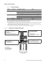
I/O Wiring – DIN CIO Transmitters
I/O Wiring – DIN CIO Return PolicySpecificationsI/O Wiring – DIN AN
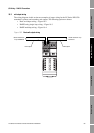
10.4 Frequency output wiring
Frequency output wiring depends on whether you are wiring terminals 23 and 24 (Channel B) or
terminals 31 and 32 (Channel C), and also on whether you have configured the terminals for internal
or external power. The following diagrams are examples of proper wiring for these configurations:
• Channel B, internal power – Figure 10-5
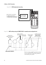
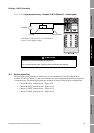
• Channel B, external power – Figure 10-6
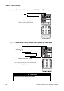
• Channel C, internal power – Figure 10-7
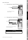
• Channel C, external power – Figure 10-8
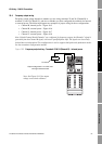
Note: If both Channel B and Channel C are configured for frequency output, the Channel C signal is
generated from the Channel B signal, with a user-specified phase shift. The signals are electrically
isolated but not independent. This configuration is used to support dual-pulse and quadrature modes.
See the transmitter configuration manual.
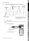
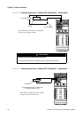
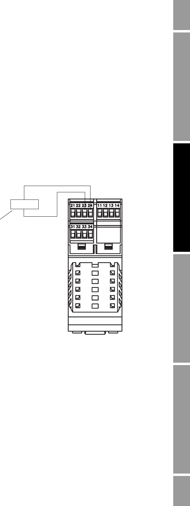
Figure 10-5 Frequency output wiring – Terminals 23 & 24 (Channel B) – Internal power
Counter
000042
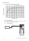
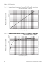
Note: See Figure 10-13 for output
voltage versus load resistance.
+
–
Output voltage level is +15 VDC ±3%
with high resistance load.