


32 LF-Series Flowmeters: Sensor/Transmitter Installation
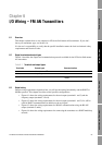
I/O Wiring – FM CIO Transmitters
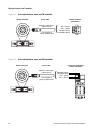
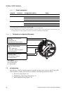
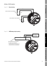
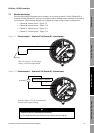
Figure 7-1 Configuration of configurable I/O terminals
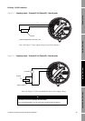
7.3 mA output wiring
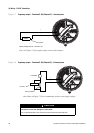
The following 4–20 mA wiring diagrams are examples of proper basic wiring for the LF-Series FM
CIO transmitter’s primary and secondary mA outputs. The following options are shown:
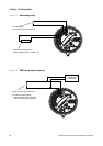
• Basic mA wiring (Figure 7-2)
• HART/analog single-loop wiring (Figure 7-3)
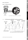
• HART multidrop wiring (Figure 7-4)
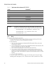
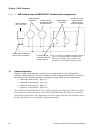
Table 7-1 Channel configuration
Channel Terminals Configuration options Power
A 1 & 2 mA output with HART/Bell 202
(1)
(1) The Bell 202 signal is superimposed on the mA output.
Internal
B 3 & 4 • mA output (default) Internal
• Frequency output Internal or external
(2)
(2) You must provide power to the outputs when a channel is set to external power.
• Discrete output Internal or external
C 5 & 6 • Frequency output (default)
(3)
(3) When configured for two frequency outputs (dual pulse), frequency output 2 is generated from the same signal that is sent
to the first frequency output. Frequency output 2 is electrically isolated but not independent.
Internal or external
• Discrete output Internal or external
• Discrete input Internal or external
Terminals 1 and 2 (Channel A)
mA1 output
Internal power only
HART (Bell 202) communications
Terminals 3 and 4 (Channel B)
mA2 output OR FO OR DO1
Power:
• mA – internal only
• FO or DO – internal or external
No communications
Terminals 5 and 6 (Channel C)
FO OR DO2 OR DI
Power: internal or external
No communications
mA = milliamp
FO = frequency output
DO = discrete output
DI = discrete input
+
–
+
–
+
–