


LF-Series Flowmeters: Sensor/Transmitter Installation 37
I/O Wiring – FM CIO Transmitters
I/O Wiring – FM AN I/O Wiring – FM FB and PAI/O Wiring – FM CIOSensor Wiring
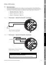
7.5 Discrete output wiring
Discrete output (DO) wiring depends on whether you are wiring terminals 3 and 4 (Channel B) or
terminals 5 and 6 (Channel C), and also on whether you have configured the terminals for internal or
external power. The following diagrams are examples of proper wiring for these configurations:
• Channel B, internal power – Figure 7-9
• Channel B, external power – Figure 7-10
• Channel C, internal power – Figure 7-11
• Channel C, external power – Figure 7-12
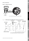
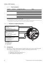
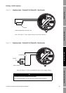
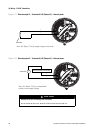
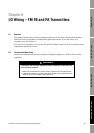
Figure 7-9 Discrete output 1 – Terminals 3 & 4 (Channel B) – Internal power
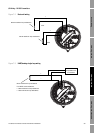
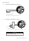
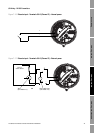
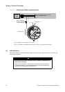
Figure 7-10 Discrete output 1 – Terminals 3 & 4 (Channel B) – External power
Total load
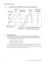
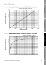
Note: See Figure 7-13 for output
voltage versus load information.
+
–
3–30 VDC
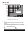
Note: See Figure 7-15 for recommended
resistor versus supply voltage.
CAUTION
Excessive current will damage the transmitter.
Do not exceed 30 VDC input. Terminal current must be less than 500 mA.
+
–
+
–
Pull-up resistor or DC relay