


14 LF-Series Flowmeters: Sensor/Transmitter Installation
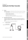
Installing the Field-Mount Transmitter
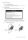
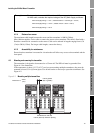
The transmitter has both an internal and an external grounding screw (see Figures 3-3 and 3-4).
Ground the transmitter according to applicable local standards.
3.5 Supplying power
In all installations, power must be provided to the transmitter. Refer to Section 3.2.3 for information
on the transmitter’s power supply requirements.
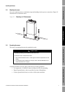
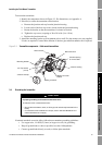
1. Connect the power supply to terminals 9 and 10, under the Warning flap (see Figure 3-4).
Terminate the positive (line) wire on terminal 10 and the return (neutral) wire on terminal 9.
2. Ground the power supply using the equipment ground, also under the Warning flap.
3. A user-supplied switch may be installed in the power supply line. For compliance with low-
voltage directive 73/23/EEC (European installations), a switch in close proximity to the
transmitter is required.
Figure 3-4 Wiring the transmitter power supply
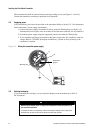
3.6 Rotating the display
If your transmitter has a display, you can rotate the display on the transmitter up to 360° in
90° increments.
WARNING
Removing the display cover in explosive atmospheres while the power is on
can cause an explosion.
To reduce the risk of an explosion, before removing the display cover in explosive
atmospheres, be sure to shut off the power and wait five minutes.
Equipment
ground
9
10
Warning flap