


LF-Series Flowmeters: Sensor/Transmitter Installation 23
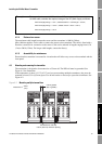
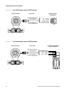
I/O Wiring – FM AN I/O Wiring – FM FB and PAI/O Wiring – FM CIOSensor Wiring
Chapter 5
Wiring the Sensor to the Transmitter
5.1 Overview
This chapter describes how to connect Micro Motion LF-Series sensors to LF-Series transmitters.
This chapter also describes how to connect the LF-Series sensor to a remote host, for use in
MVD Direct Connect installations.
5.2 Cable types
Micro Motion offers 4-wire cable with a factory-installed Eurofast connector.
5.3 Wiring to FM or DIN transmitters
To connect the cable, follow the steps below.
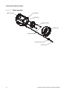
1. To connect the cable to the sensor, plug the Eurofast connector onto the top of the sensor
connection. The connector is keyed for appropriate orientation.
2. Identify the wires in the 4-wire cable. The 4-wire cable supplied by Micro Motion consists of
one pair of 18 AWG (0,75 mm
2
) wires (brown and black), which should be used for the VDC
connection, and one pair of 22 AWG (0,35 mm
2
) wires (blue and white), which should be used
for the RS-485 connection.
3. To connect:
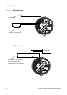
• To a field-mount transmitter, connect the four wires from the sensor to terminals 1–4 on
the mating connector of the transmitter. See Figure 5-1. Do not ground the shield, braid, or
drain wire(s) at the transmitter.
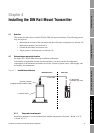
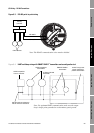
• To a DIN rail mount transmitter, connect the four wires from the sensor to terminals 1–4
on the transmitter. See Figure 5-2. Do not ground the shield, braid, or drain wire(s) at the
transmitter.
CAUTION
Large electromagnetic fields can interfere with flowmeter communication
signals.
Improper installation of cable or conduit can cause measurement error or flowmeter
failure. To reduce the risk of measurement error or flowmeter failure, keep cable or
conduit away from devices such as transformers, motors, and power lines which
produce large electromagnetic fields.