


LF-Series Flowmeters: Sensor/Transmitter Installation 75
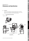
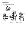
Dimensions and Specifications
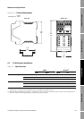
I/O Wiring – DIN CIO Return PolicySpecificationsI/O Wiring – DIN AN
Output option code 6
(F
OUNDATION fieldbus)
Transmitters are registered with the Fieldbus Foundation, and conform to the
FOUNDATION fieldbus H1 protocol specification.
Input frequency from sensor:
• Mass flow: 20 Hz
• Volume flow: 20 Hz
•Density: 20Hz
• Temperature: 1Hz
Analog input function blocks:
• Cycle time: Host dependent
• Update rate: 50 milliseconds
• Refresh rate: Host dependent
Output option code 7
(Profibus-PA)
Transmitters are registered with the Profibus Organization, and fulfill the
requirements of the Profibus-PA Profile for Process Control Devices.
Input frequency from sensor:
• Mass flow: 20 Hz
• Volume flow: 20 Hz
•Density: 20Hz
• Temperature: 1Hz
Analog input function blocks:
• Cycle time: Host dependent
• Update rate: 50 milliseconds
• Refresh rate: Host dependent
Siemens Simatic PDM required for configuration.
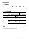
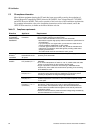
Table A-13 FM transmitter power supply
Self-switching AC/DC input, automatically recognizes supply voltage.
Complies with low voltage directive 73/23/EEC per IEC 61010-1
Installation (Overvoltage) Category II, Pollution Degree 2.
The transmitter fieldbus circuit is passive, and draws its power from the fieldbus segment. Current draw from the fieldbus
segment is 11.5 mA.
AC power 85 to 265 VAC, 50/60 Hz, 6 watts typical, 11 watts maximum
DC power 18 to 100 VDC, 6 watts typical, 11 watts maximum
At startup, transmitter power source must provide a minimum of 1.5 amperes of
short-term current at a minimum of 18 volts at the transmitter's power input
terminals.
Minimum 22 VDC with 1000 feet of 18 AWG (300 meters of 0,8 mm
2
) power supply
cable
Fuse IEC 127-1.25 fuse, slowblow
Table A-14 FM transmitter environmental limits
Ambient temperature limits Operating and storage: –40 to +140 °F (–40 to +60 °C)
Display responsiveness decreases and display may become difficult to read below
–4 °F (–20 °C). Above 131 °F (55 °C), some darkening of the display might occur.
ATEX requires limiting ambient temperature to below 131 °F (55 °C).
Humidity limits 5 to 95% relative humidity, non-condensing at 140 °F (60 °C)
Vibration limits Meets IEC68.2.6, endurance sweep, 5 to 2000 Hz, 50 sweep cycles at 1.0 g.
Table A-15 FM transmitter environmental effects
EMI effects Meets EMC directive 89/336/EEC per EN 61326 Industrial
Ambient temperature effect On analog outputs ±0.005% of span per °C
Table A-12 FM transmitter digital communications continued