


LF-Series Flowmeters: Sensor/Transmitter Installation 13
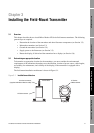
Installing the Field-Mount Transmitter
Installing the Sensor Installing the DIN TransmitterInstalling the FM TransmitterBefore You Begin
To mount the transmitter:
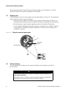
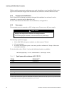
1. Identify the components shown in Figure 3-3. For dimensions, see Appendix A.
2. If desired, re-orient the transmitter on the bracket.
a. Remove the junction end-cap from the junction housing.
b. Loosen each of the four cap screws (4 mm) inside the junction housing.
c. Rotate the bracket so that the transmitter is oriented as desired.
d. Tighten the cap screws, torquing to 30 to 38 in-lbs (3 to 4 N-m).
e. Replace the junction end-cap.
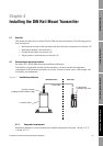
3. Attach the mounting bracket to an instrument pole or wall. For pipe mount, two user-supplied
U-bolts are required. Contact Micro Motion to obtain a pipe-mount installation kit if required.
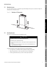
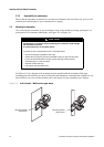
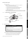
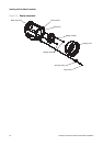
Figure 3-3 Transmitter components – field-mount transmitters
3.4 Grounding the transmitter
If national standards are not in effect, follow these transmitter grounding guidelines:
• Use copper wire, 14 AWG (2,5 mm
2
) or larger wire size, for grounding.
• Keep all ground leads as short as possible, less than 1 Ω impedance.
• Connect ground leads directly to earth, or follow plant standards.
CAUTION
Improper grounding could cause measurement error.
To reduce the risk of measurement error:
• Ground the transmitter to earth, or follow ground network requirements for the
facility.
• For hazardous area installations in Europe, refer to standard EN 60079-14 if
national standards do not apply.
Ground screw
Mounting bracket
Main enclosure
Junction housing
Mating connector
socket
Mating connector
Junction end-cap
4 X Cap screws
(4 mm)
Conduit opening
for 4-wire cable