


34 LF-Series Flowmeters: Sensor/Transmitter Installation
I/O Wiring – FM CIO Transmitters
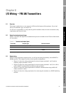
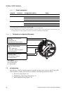
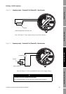
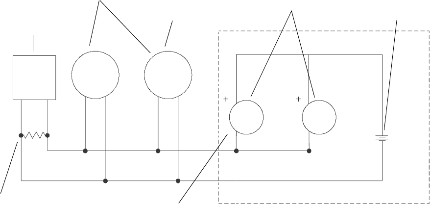
Figure 7-4 HART multidrop wiring with SMART FAMILY
™
transmitters and a configuration tool
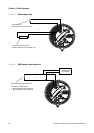
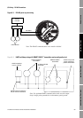
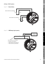
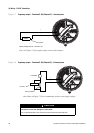
7.4 Frequency output wiring
Frequency output wiring depends on whether you are wiring terminals 3 and 4 (Channel B) or
terminals 5 and 6 (Channel C), and also on whether you have configured the terminals for internal or
external power. The following diagrams are examples of proper wiring for these configurations:
• Channel B, internal power – Figure 7-5
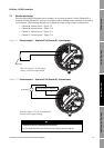
• Channel B, external power – Figure 7-6
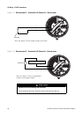
• Channel C, internal power – Figure 7-7
• Channel C, external power – Figure 7-8
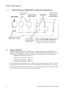
Note: If both Channel B and Channel C are configured for frequency output, the Channel C signal is
generated from the Channel B signal, with a user-specified phase shift. The signals are electrically
isolated but not independent. This configuration is used to support dual-pulse and quadrature modes.
For more information, see the transmitter configuration manual.
HART-compatible
host or controller
HART-compatible
transmitters
SMART FAMILY
™
transmitters
Note: For optimum HART communication,
make sure the output loop is single-point-
grounded to an instrument-grade ground.
24 VDC loop power
supply required for
HART 4–20 mA
passive transmitters
LF-Series FM CIO
transmitter (internally
powered outputs)
600 Ω maximum resistance
250 Ω minimum resistance
LF-Series FM CIO
transmitter (externally
powered outputs)