


70
6
INSTALLATION PROCEDURE
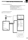
This system operates from an 11 to 30 VDC power source.
Connect the power cable as follows.
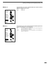
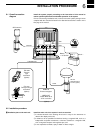
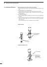
q Connect the connectorless end of the cable to the battery as shown in the over-
all connection diagram (☞ P. 68).
* Exercise care to avoid reverse connection in polarity. Reverse connection may
cause a blowout of the fuse or damage to the system.
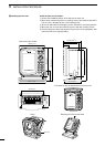
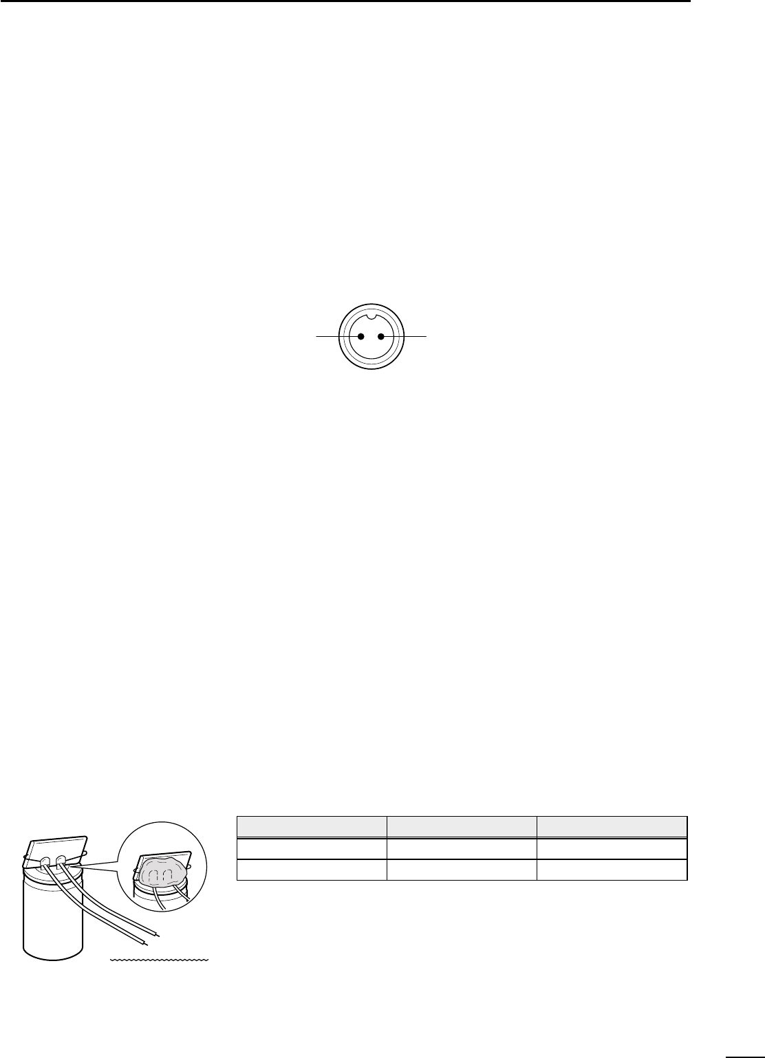
w Connect the connector end of the cable to the PWR connector located on the
rear panel of the system.
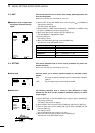
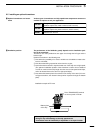
Be sure to ground the system properly.
Failure to do so may cause a malfunction or fault of the system.
To establish a ground for the system, use a ground cable of adequate size to con-
nect between the GND terminal and the engine block or hull in the shortest dis-
tance.
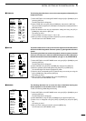
Never connect ground cables for other electronic devices to the grounding
mass that is used to ground the system.
Since GPS signals reaches the system from a distance of several hundred
miles, noise sources near the system may result in failure to take full advan-
tage of the system.
Noise sources include generator, fishfinder, radar, computer and fluorescent lamp.
The system should be placed apart from these noise sources as far as possible or
the noise sources except the generator should not be used during the use of the
system.
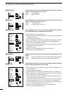
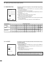
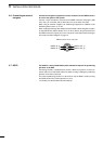
Take the following measures against noises due to the generator among others.
q Prepare an electrolytic capacitor and a film capacitor having the following ratings
depending on the system’s power source voltage.
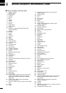
w Solder the electrolytic capacitor and film capacitor in parallel with each other.
And as shown in the figure on the left, connect lead wires to the capacitor com-
bination and cover the lead connections with silicon rubber to avoid current leak-
age.
* The lead wires must not exceed 4 in (10 cm) in length.
e Connect the positive end of the capacitor combination to the generator output
terminal and the negative end to the grounding mass such as the engine block.
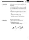
Ç Connecting the power cable
Î Connecting a ground cable
6-3 Measures against noises
from the generator
Silicon rubber
Film capacitor
Electrolytic capacitor
Must be within 10 cm each
+
_
PWR connector on the rear panel
Power source voltage
12V
24V
Electrolytic capacitor
2,200µF 35WV
2,200µF 50WV
Film capacitor
4.7µF 400WV
4.7µF 400WV