


72
6
INSTALLATION PROCEDURE
6-5 Installing an optional transducer
Various types of transducers and ship speed/water temperature sensors are
available as options to suit your application.
The performance of the fishfinder greatly depends on the installation posi-
tion of the transducer.
Transducers are mainly divided into two types: the through-the-hull type and the
transom type.
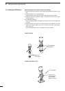
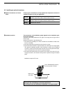
Install the transducer in the following area.
q Area where the possibility of on-screen voids due to air bubbles or water turbu-
lence is minimized;
w Area that resists being exposed to noises from the engine;
e Area where the transducer is kept horizontal even if the ship runs at high speed;
(The optimum installation position of the transducer is said to be at a distance
of a half or one-third of the ship length from the stern for low-speed small ships,
and to be located close to the stern for high-speed ships.)
r Area where the bottom plate is the thinnest in the vicinity of the stern (for inner-
hull type transducer; the ultrasonic decays when it passes through the bottom
plate).
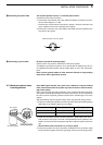
¡ Do not plug or unplug a cable into of from the TRANSDUCER connector.
Doing so may cause damage to the ship speed sensor.
¡ A transducer must be installed by a shipbuilder or an expert installer.
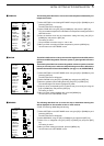
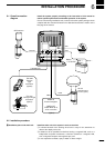
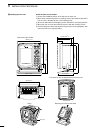
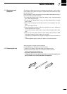
Å Optional transducers and acces-
sories
ı Installation position
EX-1010
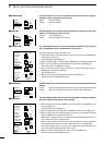
EX-1622
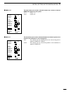
RD-200
Through-the-hull type transducer
(600W, 2 frequencies, metal enclosure, built-in sensor)
Transom type transducer
(600W, 2 frequencies, plastic enclosure, built-in sensor)
DGPS beacon receiver
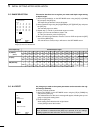
Bottom plate
of the ship
To the TRANSDUCER terminal
on the real panel of FP-561
Installation example of EX-1010