


PowerLogic™ PM5100 series user guide Chapter 3—Hardware Reference
© 2014 Schneider Electric All Rights Reserved 13
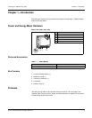
Chapter 3—Hardware Reference
This section supplements the meter’s installation sheet and provides additional
information about the meter’s physical characteristics and capabilities.
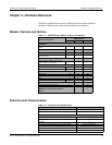
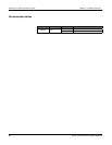
Models, Features and Options
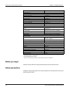
Table 3 –1: PM5100 Series - Models, Features and Options
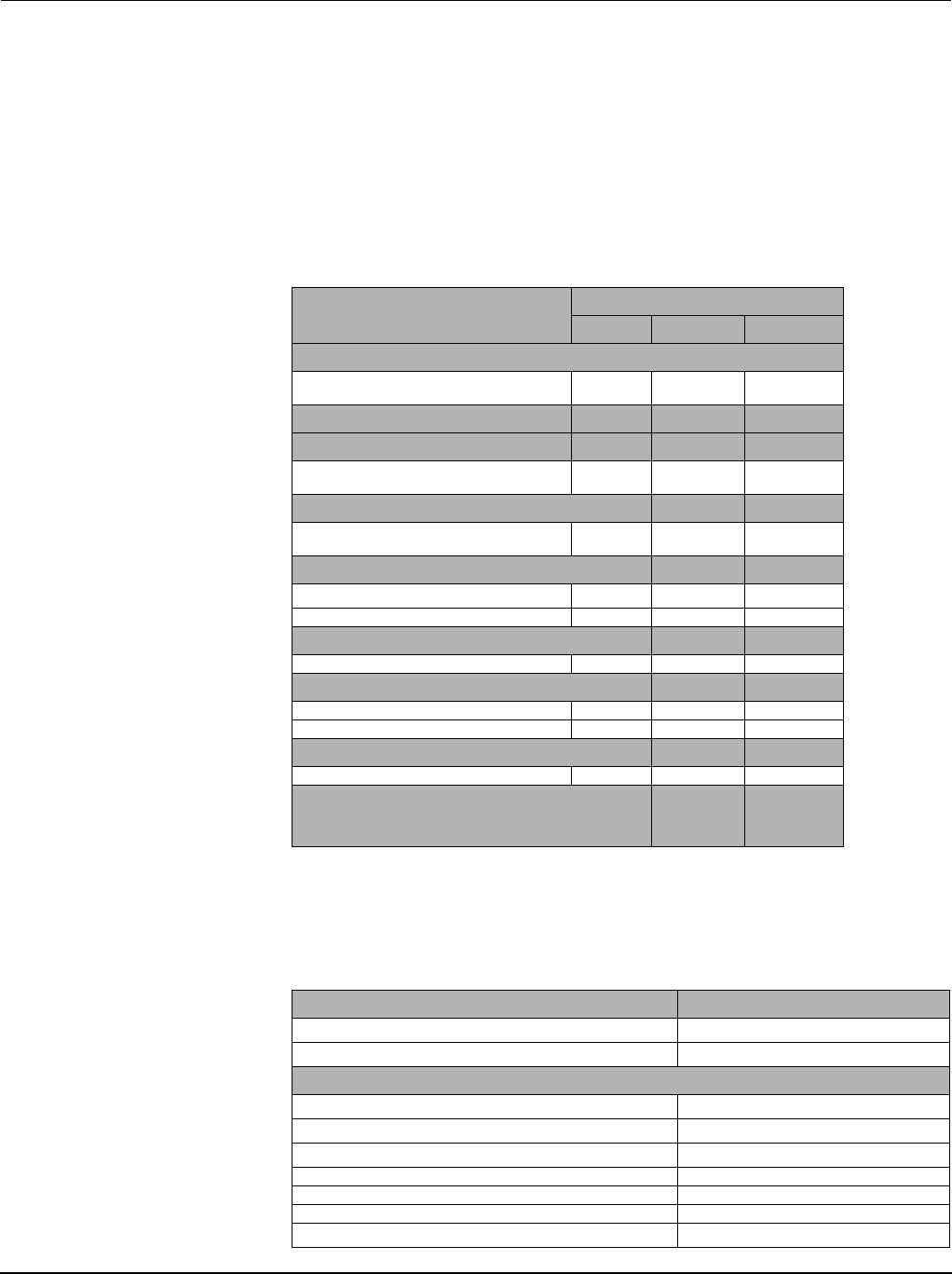
Functions and Characteristics
Table 3 –2: Functions and Characteristics
Features and Options
PM5100 series
PM5100 PM5110 PM5111
Installation
Fast installation, panel mount with integrated
display
Accuracy Cl 0.5S Cl 0.5S Cl 0.5S
Display
Backlit LCD, multilingual, bar graphs, 6 lines, 4
concurrent values
Power and energy metering
3-phase voltage, current, power, demand,
energy, frequency, power factor
Power quality analysis
THD, thd, TDD
Harmonics, individual (odd) up to 15th 15th 15th
I/Os
Digital output 1DO 1DO 1DO
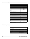
Alarms and control
Alarms 33 33 33
Set point response time, seconds 1 1 1
Communications
Serial ports with modbus protocol 0 1 1
MID ready compliance,
EN50470-1/3, Annex B and Annex D
Class C
General PM5100 Series
Use on LV and MV systems
Basic metering with THD and min/max readings
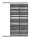
Instantaneous rms values
Current (per phase and neutral)
Voltage (total, per phase L-L and L-N)
Frequency
Real, reactive, and apparent power (Total and per phase) Signed, Four Quadrant
True Power Factor (Total and per phase) Signed, Four Quadrant
Displacement PF (Total and per phase) Signed, Four Quadrant
% Unbalanced I, V L-N, V L-L