PowerLogic™ PM5100 series user guide Chapter 3—Hardware Reference
© 2014 Schneider Electric All Rights Reserved22
NOTE:
• Clearly label the device’s disconnect circuit mechanism and install it within easy reach
of the operator.
• The fuses / circuit breakers must be rated for the installation voltage and sized for the
available fault current.
• Fuse for neutral terminal is required if the source neutral connection is not grounded.
Power system
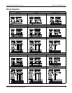
This section outlines typical requirements for wiring the voltage and current inputs of the
meter to the electrical power system.
For wiring instructions and safety precautions, see the meter installation sheet that was
shipped with your meter, or download a copy at www.schneider-electric.com.
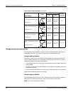
Direct connect voltage limits
You can connect the meter’s voltage inputs directly to the phase voltage lines of the
power system if the power system’s line-to-line or line-to-neutral voltages do not exceed
the meter’s direct connect maximum voltage limits. The meter's voltage measurement
inputs are rated by the manufacturer for up to 400 V L-N / 690 V L-L. However, the
maximum voltage allowed for direct connection may be lower, depending on the local
electrical codes and regulations. In US and Canada the maximum voltage on the meter
voltage measurement inputs may not exceed 347 V L-N / 600 V L-L.
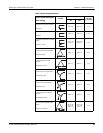
If your system voltage is greater than the specified direct connect maximum voltage, you
must use VTs (voltage transformers) to step down the voltages.
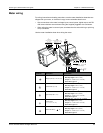
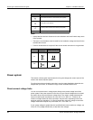
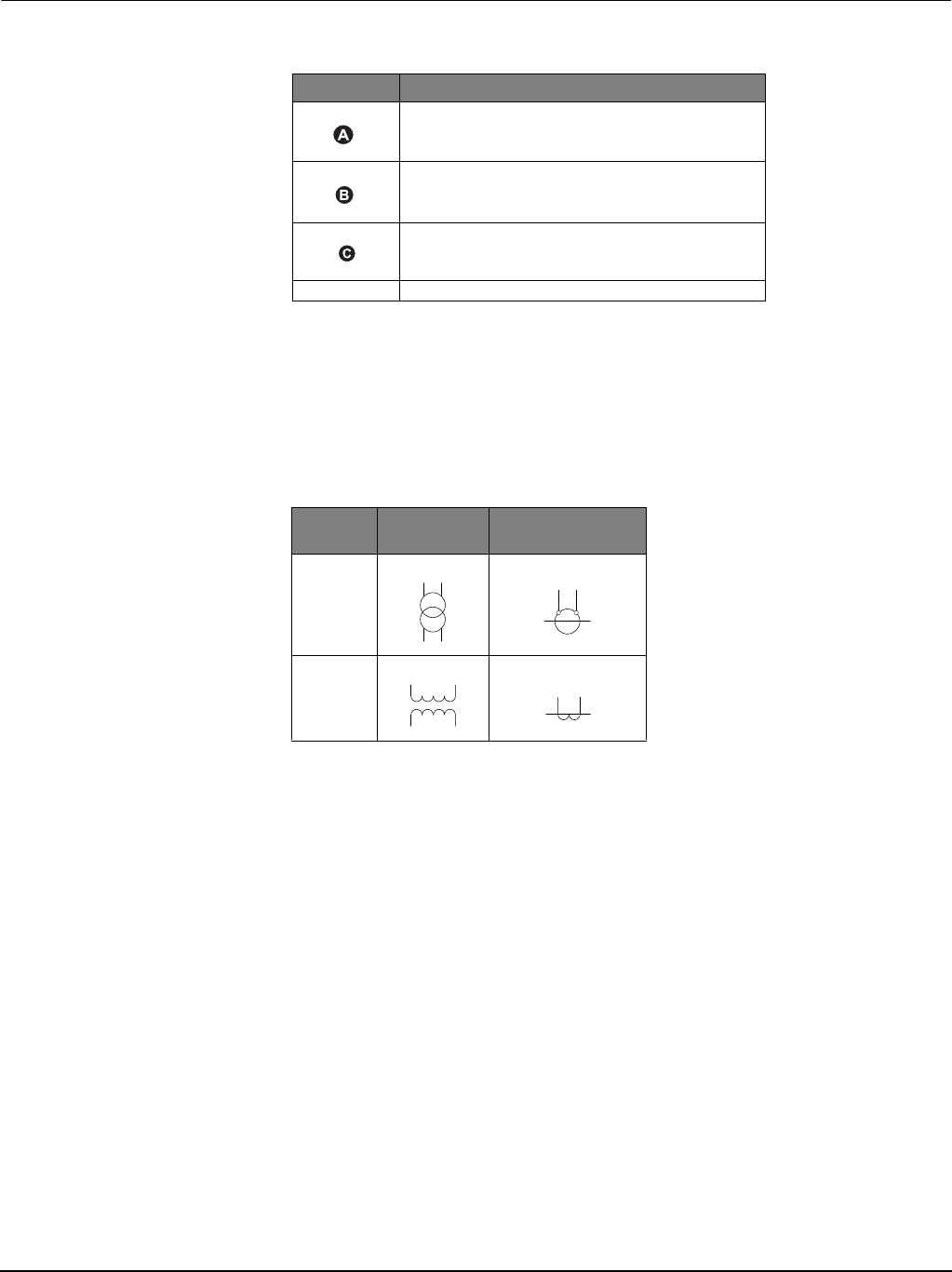
Symbol Description
500 mA fused disconnect / circuit breaker (not supplied)
Shorting block (not supplied)
PT primary fuses and disconnect switch (not supplied)
*
Indicates wiring for a balanced system
Potential
Transformer
Current Transformer
IEC
ANSI


