34 © 2014 Schneider Electric All Rights Reserved
Chapter 4—Front panel display and meter setup PowerLogic™ PM5100 series user guide
Related topics
• See “Configuring the basic setup parameters” on page 32 for meter basic setup
instructions.
Communications setup
After wiring the meter’s serial communications port, you can configure these ports so
you can connect to the meter remotely and use device configuration software such as
ION Setup to configure the meter.
Based on the reference model, the meter is equipped with the following communication
ports:
Communication ports
Setting up serial communications
The Serial Port setup screen allows you to configure the meter’s RS-485
communications port so you can use software to access the meter’s data or configure
the meter remotely.
1. Navigate to Maint > Setup.
2. Enter the setup password (default is “0000”), then press OK.
3. Press Comm.
4. Move the cursor to point to the parameter you want to modify, then press Edit.
5. Modify the parameter as required, then press OK.
6. Move the cursor to point to the next parameter you want to modify, press Edit,
make your changes, then press OK.
7. Press to exit. Press Yes to save your changes.
Reference Models Communication
PM5100 -
PM5110 RS-485
PM5111 RS-485
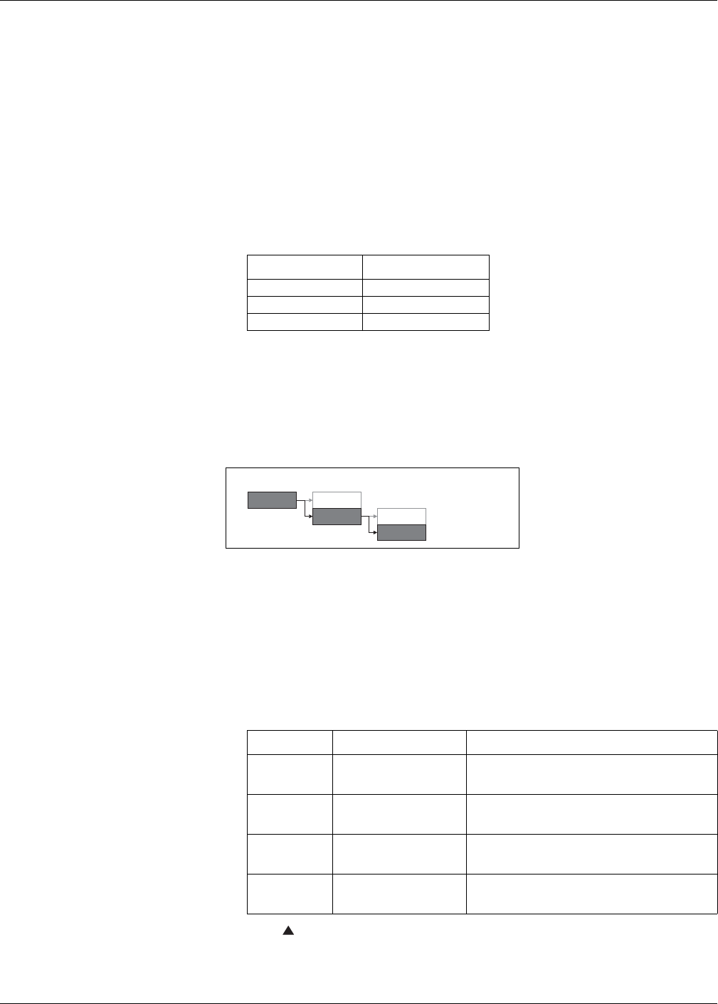
Serial communications setup menu tree
Communications setup parameters
Parameter Values Description
Protocol Modbus
The communications format used to transmit data. The
protocol must be the same for all devices in a
communications loop.
Address 1 to 247
Set the address for this device. The address must be
unique for each device in a communications loop. For
Jbus protocol, set the device ID to 255.
Baud Rate 9600, 19200, 38400
Select the speed for data transmission. The baud rate
must be the same for all devices in a communications
loop.
Parity Even, Odd, None
Select None if the parity bit is not used. The parity
setting must be the same for all devices in a
communications loop.
Maint
Reset
Setup Meter
Comm


