


76 © 2014 Schneider Electric All Rights Reserved
Chapter 10—Verifying accuracy PowerLogic™ PM5100 series user guide
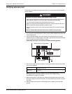
Test points
The meter should be tested at full and light loads and at lagging (inductive) power
factors to help ensure testing over the entire range of the meter. The test amperage and
voltage input rating are labeled on the meter. Refer to the installation sheet or data
sheet for your meter’s nominal current, voltage and frequency specifications.
Typical sources of test errors
If excessive errors are observed during accuracy testing, examine your test setup and
test procedures to eliminate typical sources of measurement errors:
• Loose connections of voltage or current circuits, often caused by worn-out contacts
or terminals. Inspect terminals of test equipment, cables, test harness and the meter
under test.
• Meter ambient temperature is significantly different than 23 °C (73 °F).
• Floating (ungrounded) neutral voltage terminal in any configuration with unbalanced
phase voltages.
• Inadequate meter control power, resulting in the meter resetting during the test
procedure.
• Ambient light interference or sensitivity issues with the optical sensor.
• Unstable power source causing energy pulsing fluctuations.
• Incorrect test setup: not all phases connected to the reference device or the energy
standard. All phases connected to the meter under test should also be connected to
the reference meter/standard.
• Moisture (condensing humidity), debris or pollution present in the meter under test.
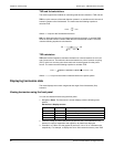
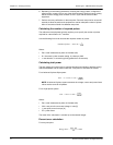
Maximum Ptot
3600 (Maximum pulse frequency)
Kmax
---------------------------------------------------------------------------------------
3600 25
9,999,999
------------------------ 0.009 kW===
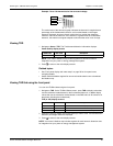
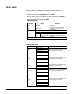
Watt-hour test points example
Watt-hour test point Sample accuracy verification test point
Full load
100% to 200% of the nominal current, 100% of the nominal voltage and nominal
frequency at unity power factor or one (1).
Light load
10% of the nominal current, 100% of the nominal voltage and nominal frequency
at unity power factor or one (1).
Inductive load (lagging
power factor)
100% of the nominal current, 100% of the nominal voltage and nominal frequency
at 0.50 lagging power factor (current lagging voltage by 60° phase angle).
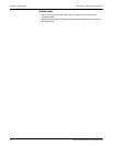
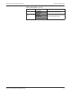
Var-hour test points example
Var-hour test point Sample accuracy verification test point
Full load
100% to 200% of the nominal current, 100% of the nominal voltage and nominal
frequency at zero power factor (current lagging voltage by 90° phase angle).
Light load
10% of the nominal current, 100% of the nominal voltage and nominal frequency
at zero power factor (current lagging voltage by 90° phase angle).
Inductive load (lagging
power factor)
100% of the nominal current, 100% of the nominal voltage and nominal frequency
at 0.87 lagging power factor (current lagging voltage by 30° phase angle).