


© 2011 Schneider Electric. All Rights Reserved.
PowerLogic
TM
Series 800 Power Meter 63230-500-225A2
Chapter 1—Introduction 3/2011
4
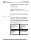
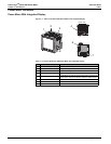
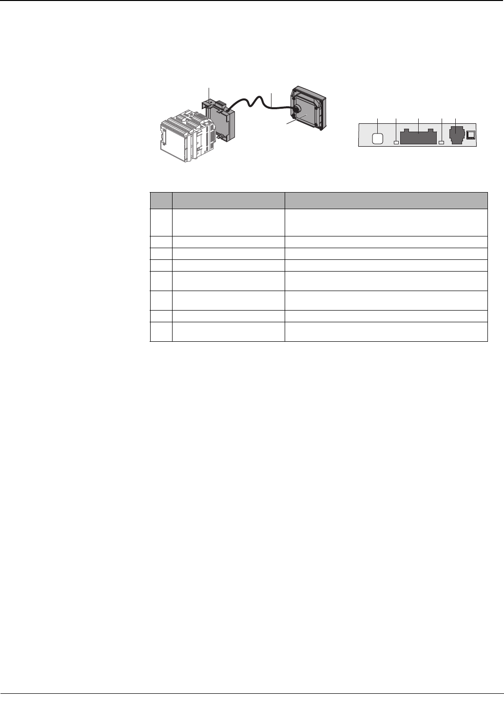
Power Meter With Remote Display
NOTE: The remote display kit (PM8RD) is used with a power meter without a display. See
“Power Meter Without Display” on page 3 for the parts of the power meter without a display.
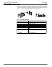
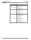
Figure 1–3: Parts of the remote display and the remote display adapter
Table 1–4: Parts of the remote display
No. Part Description
1 Remote display adapter (PM8RDA)
Provides the connection between the remote display and the
power meter. Also provides an additional RS232/RS485
connection (2- or 4-wire).
2 Cable CAB12 Connects the remote display to the remote display adapter.
3 Remote display (PM8D) Visual interface to configure and operate the power meter.
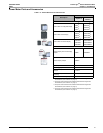
4 Communications mode button Use to select the communications mode (RS232 or RS485).
5 Communications mode LED
When lit, the LED indicates the communications port is in RS232
mode.
6 RS232/RS485 port
This port is used for communications with a monitoring and control
system. This port can be daisy-chained to multiple devices.
7 Tx/Rx Activity LED The LED flashes to indicate communications activity.
8 CAB12 port
Port for the CAB12 cable used to connect the remote display to
the remote display adapter.
2
3
1
TX/RX
4 5 6 87
PM8RDA Top View