


© 2011 Schneider Electric. All Rights Reserved.
PowerLogic
TM
Series 800 Power Meter 63230-500-225A2
Appendix D—Advanced Power Quality Evaluations 3/2011
98
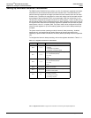
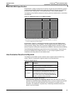
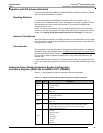
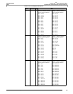
You can configure the number of allowable events per week for each range of Depth in
registers 3920 – 3927. (Default = -32768 = Pass/Fail evaluation disabled.)
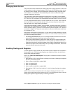
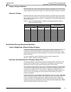
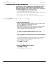
Detection of Interruptions of the Supply Voltage
The standard defines an interruption as voltage less than 1% of nominal voltage. Because
some locations require a different definition, you can configure this value in register 3906.
Interruptions are classified as “short” if duration 3 minutes or “long” otherwise. The
PM850 and the PM870 classifies interruptions as shown in Table D–9.
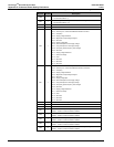
You can configure the number of allowable short interruptions per year in register 3918
(Default = -32768 = Pass/Fail evaluation disabled). You can configure the number of
allowable long interruptions per year in register 3919. (Default = -32768 = Pass/Fail
evaluation disabled.)
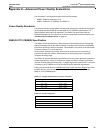
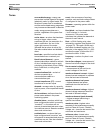
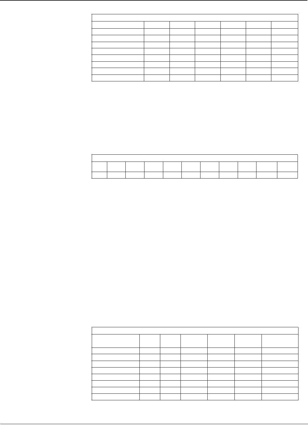
Detecting and Classifying Temporary Power Frequency Over-voltages
As stated in EN50160, a temporary power frequency over-voltage generally appears during
a fault in the electrical utility power distribution system or in a customer’s installation, and
disappears when the fault is cleared. Usually, the over-voltage may reach the value of
phase-to-phase voltage because of a shift of the neutral point of the three-phase voltage
system.
Under certain circumstances, a fault occurring upstream from a transformer will produce
temporary over-voltages on the low voltage side for the time during which the fault current
flows. Such over-voltages will generally not exceed 1.5 kV rms.
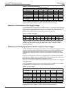
Table D–10 shows how the PM850 and the PM870 detect and classify the
over-voltages for
each phase voltage.
NOTE: Disturbance alarms are used to detect these events in the PM870. In the PM850,
standard speed over-voltage alarms are used to detect these events.
You can configure the number of allowable events per week for each range of magnitude in
registers 3930 – 3937. (Default = -32768 = Pass/Fail evaluation disabled.)
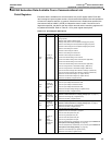
Table D–8: Voltage dip classifications
Duration (t) seconds
Depth (D) % Nominal
1 t < 3 3 t < 10 10 t < 20 20 t < 60 60 t < 180 Total
10 D < 15
15 D < 30
30 D < 45
45 D < 60
60 D < 75
75 D < 90
90 D < 99
Total
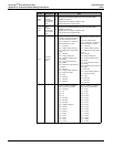
Table D–9: Voltage interruptions
Duration (t) seconds
t < 1 1 t < 2 2 t < 5
5 t <
10
10 t <
20
20 t <
60
60 t <
180
180 t <
600
600 t <
1200
1200 t
Total
Table D–10: Over-voltages
Duration (t) seconds
Magnitude (M) %
Nominal
1 t < 3 3 t < 10 10 t < 20 20 t < 60 60 t < 180 Total
110 < M 115
115 < M 130
130 < M 145
145 < M 160
160 < M 175
175 < M 200
M > 200
Total