


© 2011 Schneider Electric. All Rights Reserved.
PowerLogic
TM
Series 800 Power Meter 63230-500-225A2
Chapter 6—Alarms 3/2011
48
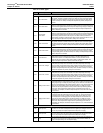
Under-voltage: Pickup and dropout setpoints are entered in volts. The per-phase under-
voltage alarm occurs when the per-phase voltage is equal to or below the pickup setpoint
long enough to satisfy the specified pickup delay (in seconds). The under-voltage alarm
clears when the phase voltage remains above the dropout setpoint for the specified dropout
delay period.
Over-voltage: Pickup and dropout setpoints are entered in volts. The per-phase over-
voltage alarm occurs when the per-phase voltage is equal to or above the pickup setpoint
long enough to satisfy the specified pickup delay (in seconds). The over-voltage alarm
clears when the phase voltage remains below the dropout setpoint for the specified dropout
delay period.
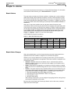
Unbalance Current: Pickup and dropout setpoints are entered in tenths of percent, based
on the percentage difference between each phase current with respect to the average of all
phase currents. For example, enter an unbalance of 7% as 70. The unbalance current
alarm occurs when the phase current deviates from the average of the phase currents, by
the percentage pickup setpoint, for the specified pickup delay. The alarm clears when the
percentage difference between the phase current and the average of all phases remains
below the dropout setpoint for the specified dropout delay period.
Unbalance Voltage: Pickup and dropout setpoints are entered in tenths of percent, based
on the percentage difference between each phase voltage with respect to the average of all
phase voltages. For example, enter an unbalance of 7% as 70. The unbalance voltage
alarm occurs when the phase voltage deviates from the average of the phase voltages, by
the percentage pickup setpoint, for the specified pickup delay. The alarm clears when the
percentage difference between the phase voltage and the average of all phases remains
below the dropout setpoint for the specified dropout delay (in seconds).
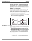
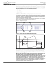
Phase Loss—Current: Pickup and dropout setpoints are entered in amperes. The phase
loss current alarm occurs when any current value (but not all current values) is equal to or
below the pickup setpoint for the specified pickup delay (in seconds). The alarm clears
when one of the following is true:
• All of the phases remain above the dropout setpoint for the specified dropout delay, or
• All of the phases drop below the phase loss pickup setpoint.
If all of the phase currents are equal to or below the pickup setpoint, during the pickup
delay, the phase loss alarm will not activate. This is considered an under current condition.
It should be handled by configuring the under current alarm functions.
Phase Loss—Voltage: Pickup and dropout setpoints are entered in volts. The phase loss
voltage alarm occurs when any voltage value (but not all voltage values) is equal to or
below the pickup setpoint for the specified pickup delay (in seconds). The alarm clears
when one of the following is true:
• All of the phases remain above the dropout setpoint for the specified dropout delay (in
seconds), OR
• All of the phases drop below the phase loss pickup setpoint.
If all of the phase voltages are equal to or below the pickup setpoint, during the pickup
delay, the phase loss alarm will not activate. This is considered an under voltage condition.
It should be handled by configuring the under voltage alarm functions.
Reverse Power: Pickup and dropout setpoints are entered in kilowatts or kVARs. The
reverse power alarm occurs when the power flows in a negative direction and remains at or
below the negative pickup value for the specified pickup delay (in seconds). The alarm
clears when the power reading remains above the dropout setpoint for the specified
dropout delay (in seconds).
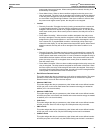
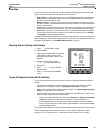
Phase Reversal: Pickup and dropout setpoints do not apply to phase reversal. The phase
reversal alarm occurs when the phase voltage rotation differs from the default phase
rotation. The power meter assumes that an ABC phase rotation is normal. If a CBA phase
rotation is normal, the user must change the power meter’s phase rotation from ABC
(default) to CBA. To change the phase rotation from the display, from the main menu select
Setup > Meter > Advanced. For more information about changing the phase rotation setting
of the power meter, refer to “ADVAN (Advanced) Power Meter Setup Features” on
page 19.