


63230-500-225A2 PowerLogic
TM
Series 800 Power Meter
3/2011 Appendix A—Instrument Transformer Wiring: Troubleshooting Tables
© 2011 Schneider Electric All Rights Reserved
73
Appendix A—Instrument Transformer Wiring: Troubleshooting Tables
Abnormal readings in an installed meter can sometimes signify improper wiring. This
appendix is provided as an aid in troubleshooting potential wiring problems.
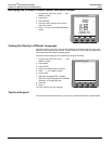
Using This Appendix
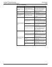
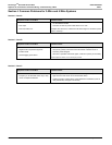
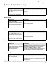
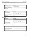
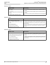
The following pages contain “Case” tables arranged in sections. These tables show a
variety of symptoms and probable causes.
Section I: Check these tables first. These are common problems for 3-wire and 4-wire
systems that can occur regardless of system type.
Section II: Check these tables if troubleshooting more complex 3-wire systems.
Section III: Check these tables if troubleshooting more complex 4-wire systems.
The symptoms listed are “ideal,” and some judgment should be exercised when
troubleshooting. For example, if the kW reading is 25, but you know that it should be about
300 kW, go to a table where “kW = 0” is listed as one of the symptoms.
Because it is nearly impossible to address all combinations of multiple wiring mistakes or
other problems that can occur (e.g., blown PT fuses, missing PT neutral ground
connection), this guide generally addresses only one wiring problem at a time.
Before trying to troubleshoot wiring problems, it is imperative that all instantaneous
readings be available for reference. Specifically, those readings should include the
following:
• line-to-line voltages
• line-to-neutral voltages
• phase currents
• power factor
• kW
• kVAR
• kVA
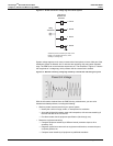
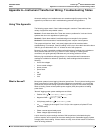
What is Normal? Most power systems have a lagging (inductive) power factor. The only time a leading power
factor is expected is if power factor correction capacitors are switched in or over-excited
synchronous motors with enough capacitive kVARS are on-line to overcorrect the power
factor to leading. Some uninterruptable power supplies (UPS) also produce a leading
power factor.
"Normal" lagging power system readings are as follows:
• Positive kW =
• Negative kVAR =
• kVA (always positive) =
•
= lagging in the range 0.70 to 1.00 (for 4-wire systems, all phase PFs are
about the same)
• Phase currents approximately equal
• Phase voltages approximately equal
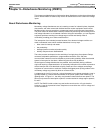
A quick check for proper readings consists of kW comparisons (calculated using the
previous equation and compared to the meter reading) and a reasonable lagging 3-phase
average power factor reading. If these checks are okay, there is little reason to continue to
check for wiring problems.
3 V
AB
I
3Avg
PF
3Avg
1000
kVA
2
kW
2
–1000
3V
AB
I
3Avg
1000
PF
3Avg