


© 2011 Schneider Electric. All Rights Reserved.
PowerLogic
TM
Series 800 Power Meter 63230-500-225A2
Chapter 5—Input/Output Capabilities 3/2011
40
Demand Synch Pulse Input
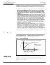
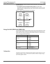
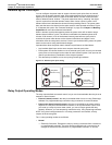
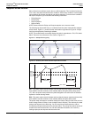
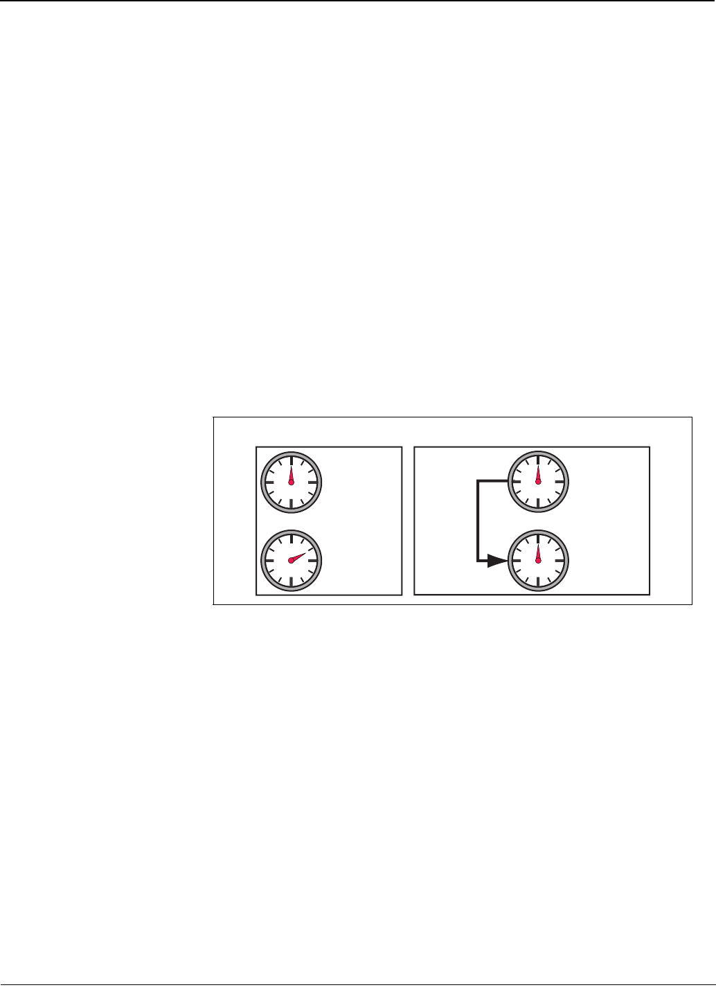
You can configure the power meter to accept a demand synch pulse from an external
source, such as another demand meter. By accepting demand synch pulses through a
digital input, the power meter can make its demand interval “window” match the other
meter’s demand interval “window.” The power meter does this by “watching” the digital
input for a pulse from the other demand meter. When it sees a pulse, it starts a new
demand interval and calculates the demand for the preceding interval. The power meter
then uses the same time interval as the other meter for each demand calculation. Figure
5–2 illustrates this option. See “Demand Readings” on page 30 in Chapter 4—Metering
Capabilities for more about demand calculations.
When in demand synch pulse operating mode, the power meter will not start or stop a
demand interval without a pulse. The maximum allowable time between pulses is 60
minutes. If 66 minutes (110% of the demand interval) pass before a synch pulse is
received, the power meter throws out the demand calculations and begins a new
calculation when the next pulse is received. Once in synch with the billing meter, the power
meter can be used to verify peak demand charges.
Important facts about the power meter’s demand synch feature are listed below:
• Any installed digital input can be set to accept a demand synch pulse.
• Each system can choose whether to use an external synch pulse, but only one demand
synch pulse can be brought into the meter for each demand system. One input can be
used to synchronize any combination of the demand systems.
• The demand synch feature can be set up using PowerLogic software.
Relay Output Operating Modes
The relay output defaults to external control, but you can choose whether the relay is set to
external or internal control:
• External (remote) control—the relay is controlled either from a PC using PowerLogic
software or
a programmable logic controller using commands via communications.
• Power meter alarm (internal) control—the relay is controlled by the power meter in
response to a set-point controlled alarm condition, or as a pulse initiator output. Once
you’ve set up a relay for power meter control, you can no longer operate the relay
remotely. However, you can temporarily override the relay, using PowerLogic software.
NOTE: If any basic setup parameters or I/O setup parameters are modified, all relay
outputs will be de-energized.
The 11 relay operating modes are as follows:
• Normal
— Externally Controlled: Energize the relay by issuing a command from a remote
PC
or programmable controller. The relay remains energized until a command to de-
energize is issued from the remote
PC or programmable controller, or until the
Figure 5–2: Demand synch pulse timing
PLSD110140
Normal Demand Mode External Synch Pulse Demand Timing
Billing Meter
Demand Timing
Power Meter
Demand Timing
Billing Meter
Demand Timing
Power Meter
Demand Timing
(Slave to Master)
Utility Meter
Synch Pulse