


© 2011 Schneider Electric. All Rights Reserved.
63230-500-225A2 PowerLogic
TM
Series 800 Power Meter
3/2011 Appendix C—Using the Command Interface
85
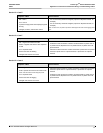
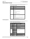
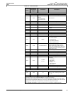
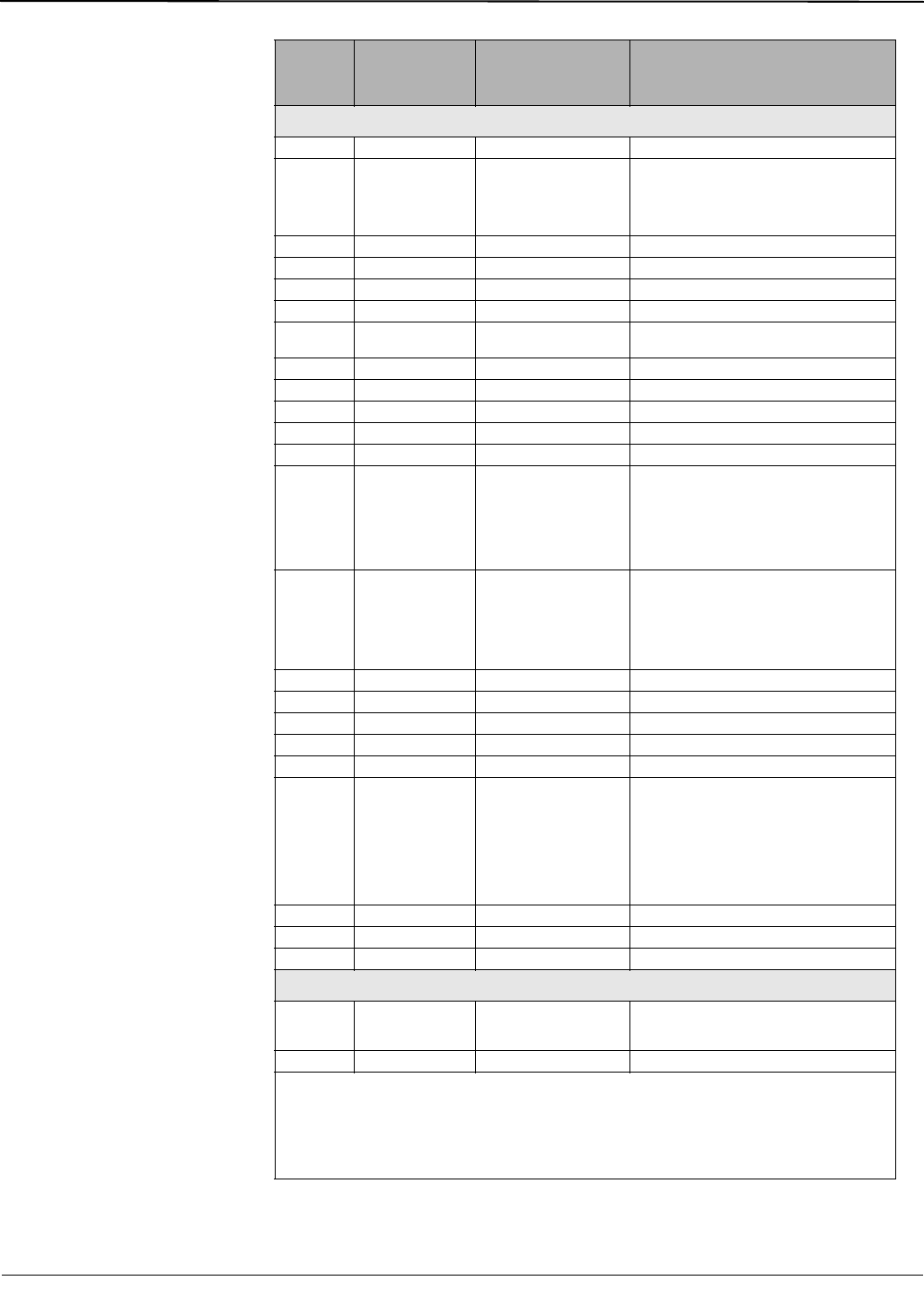
Resets
1522 None None Resets the alarm history log.
4110 8001
0 = Present and previous
months
1 = Present month
2 = Previous month
Resets min/max.
5110 None None Resets all demand registers.
5111 None None Resets current demand.
5113 None None Resets power demand.
5114 None None Resets input demand.
5115 None None
Resets generic demand for first group of 10
quantities.
5210 None None Resets all min/max demand.
5211 None None Resets current min/max demand.
5213 None None Resets power min/max demand.
5214 None None Resets input min/max demand.
5215 None None Resets generic 1 min/max demand.
5910 8001 Bitmap
Start new demand interval.
Bit 0 = Power Demand
1 = Current Demand
2 = Input Metering Demand
3 = Generic Demand Profile
6209 8019 I/O Data Pointer
➁
Preset Accumulated Energies
Requires the IO Data Pointer to point to
registers where energy preset values are
entered. All Accumulated energy values must
be entered in the order in which they occur in
registers 1700 to 1727.
6210 None None Clears all energies.
6211 None None Clears all accumulated energy values.
6212 None None Clears conditional energy values.
6213 None None Clears incremental energy values.
6214 None None Clears input metering accumulation.
6215 None
1 = IEEE
2 = IEC
Resets the following parameters to IEEE or
IEC defaults:
1. Phase labels
2. Menu labels
3. Harmonic units
4. PF sign
5. THD denominator
6. Date Format
6320 None None Disables conditional energy accumulation.
6321 None None Enables conditional energy accumulation.
6910 None None Starts a new incremental energy interval.
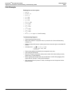
Files
7510 8001 1–3
Triggers data log entry. Bitmap where Bit 0 =
Data Log 1, Bit 1 = Data Log 2, Bit 2 = Data
Log 3, etc.
7511 8001 File Number Triggers single data log entry.
Table C–2: Command Codes
Command
Code
Command
Parameter
Register
Parameters Description
➀ You must write to register 8001 the number that identifies which output you would like to use. To determine
the identifying number, refer to“I/O Point Numbers” on page 86 for instructions.
➁ Data buffer location (register 8019) is the pointer to the first register where data will be stored. By default,
return data begins at register 8020, although you can use any of the registers from 8020–8149. Take care when
assigning pointers. Values may be corrupted if two commands are using the same register.
Refer to “Register List Access” on page 79 for instructions on accessing the complete register list.