


© 2011 Schneider Electric. All Rights Reserved.
63230-500-225A2 PowerLogic
TM
Series 800 Power Meter
3/2011 Chapter 5—Input/Output Capabilities
39
Chapter 5—Input/Output Capabilities
Digital Inputs
The power meter includes one solid-state digital input. A digital input is used to detect
digital signals. For example, the digital input can be used to determine circuit breaker
status, count pulses, or count motor starts. The digital input can also be associated with an
external relay. You can log digital input transitions as events in the power meter’s on-board
alarm log. The event is date and time stamped with resolution to the second. The power
meter counts OFF-to-ON transitions for each input. You can view the count for each input
using the Digital Inputs screen, and you can reset this value using the command interface.
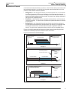
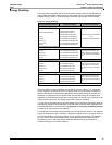
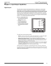
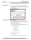
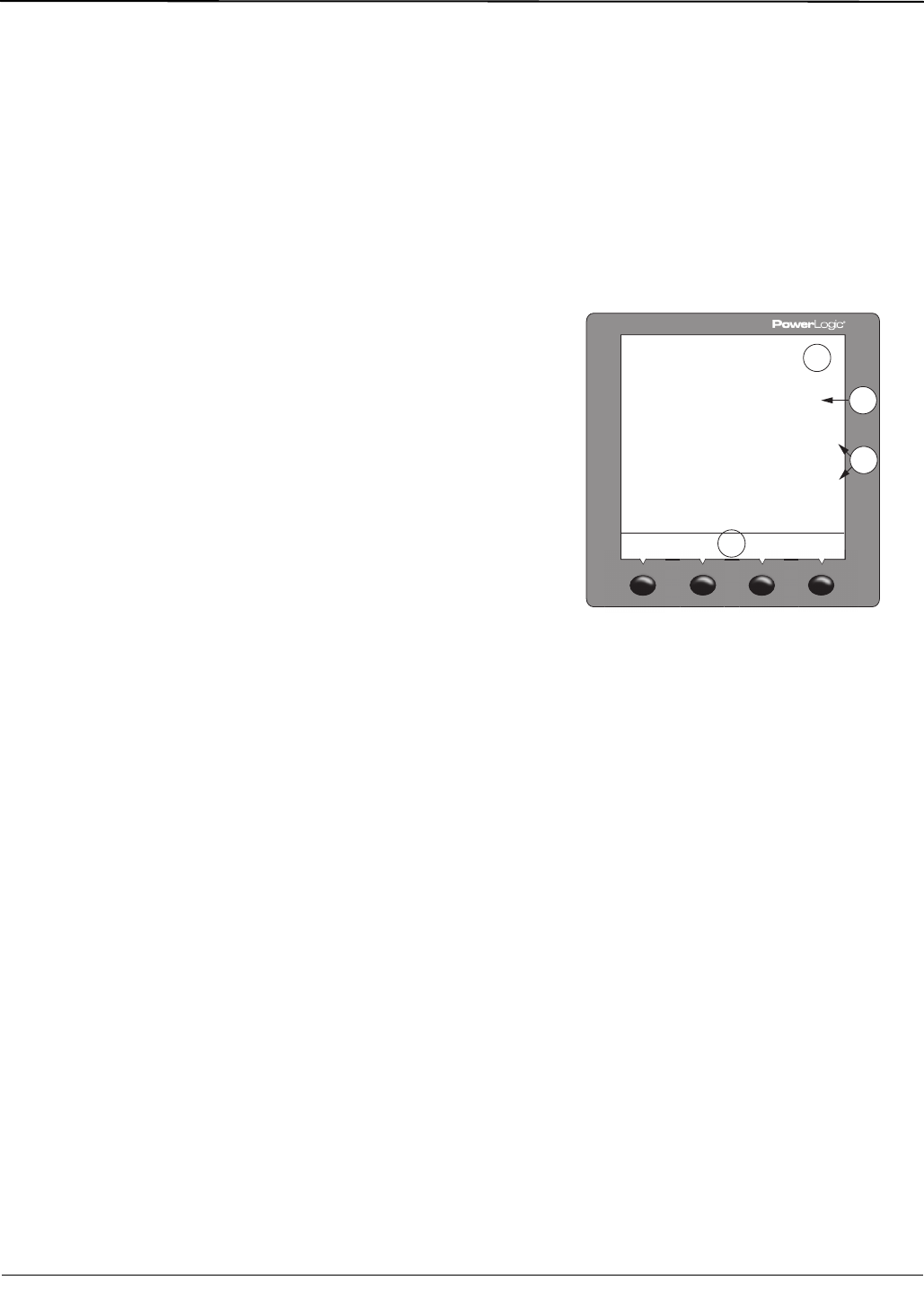
Figure 5–1 is an example of the Digital Inputs screen.
The digital input has three operating modes:
• Normal—Use the normal mode for simple on/off digital inputs. In normal mode, digital
inputs can be used to count KY pulses for demand and energy calculation.
• Demand Interval Synch Pulse—you can configure any digital input to accept a
demand synch pulse from a utility demand meter (see “Demand Synch Pulse Input” on
page 40 of this chapter for more about this topic). For each demand profile, you can
designate only one input as a demand synch input.
• Conditional Energy Control—you can configure one digital input to control conditional
energy (see “Reactive energy accumulates in four quadrants” on page 36 in Chapter
4—Metering Capabilities for more about conditional energy).
NOTE: By default, the digital input is named DIG IN S02 and is set up for normal mode.
For custom setup, use PowerLogic software to define the name and operating mode of the
digital input. The name is a 16-character label that identifies the digital input. The operating
mode is one of those listed above.
Figure 5–1: Digital Inputs Screen
A. Lit bargraph indicates that the input is
ON. For analog inputs or outputs, the
bargraph indicates the output
percentage.
B. SI is common to all meters and
represents standard digital input.
C. A-S1 and A-S2 represent I/O point
numbers on the first (A) module.
D. Use the arrow buttons to scroll through
the remaining I/O points. Point numbers
beginning with “B” are on the second
module.
D
B
A
C
PLSD110233