


© 2011 Schneider Electric. All Rights Reserved.
PowerLogic
TM
Series 800 Power Meter 63230-500-225A2
Chapter 10—Maintenance and Troubleshooting 3/2011
72
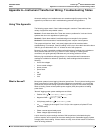
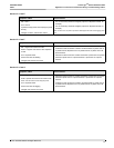
Table 10–1: Troubleshooting
Potential Problem Possible Cause Possible Solution
The maintenance icon is
illuminated on the power
meter display.
When the maintenance icon is
illuminated, it indicates a potential
hardware or firmware problem in the
power meter.
Go to DIAGNOSTICS > MAINTENANCE.
Error messages display to indicate the
reason the icon is illuminated. Note these
error messages and call Technical
Support, or contact your local sales
representative for assistance.
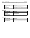
The display shows error
code 3.
Loss of control power or meter
configuration has changed.
Set date and time.
The display is blank after
applying control power to
the power meter.
The power meter may not be
receiving the necessary power.
• Verify that the power meter line (L) and
neutral (N) terminals (terminals 25 and
27) are receiving the necessary power.
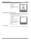
• Verify that the heartbeat LED is
blinking.
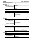
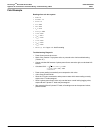
The data being displayed is
inaccurate or not what you
expect.
Power meter is grounded incorrectly.
Verify that the power meter is grounded as
described in “Grounding the Power Meter”
in the installation manual.
Incorrect setup values.
Check that the correct values have been
entered for power meter setup parameters
(CT and PT ratings, System Type, Nominal
Frequency, and so on). See “Power Meter
Setup” on page 13 for setup instructions.
Incorrect voltage inputs.
Check power meter voltage input terminals
L (8, 9, 10, 11) to verify that adequate
voltage is present.
Power meter is wired improperly.
Check that all CTs and PTs are connected
correctly (proper polarity is observed) and
that they are energized. Check shorting
terminals. See “Instrument Transformer
Wiring: Troubleshooting Tables” on
page 73. Initiate a wiring check using
PowerLogic software.
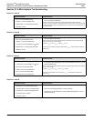
Cannot communicate with
power meter from a remote
personal computer.
Power meter address is incorrect.
Check to see that the power meter is
correctly addressed. See “COMMS
(Communications) Setup” on page 15 for
instructions.
Power meter baud rate is incorrect.
Verify that the baud rate of the power
meter matches the baud rate of all other
devices on its communications link. See
“COMMS (Communications) Setup” on
page 15 for instructions.
Communications lines are improperly
connected.
Verify the power meter communications
connections. Refer to the PM800-Series
Installation Guide.
Communications lines are improperly
terminated.
Check to see that a multipoint
communications terminator is properly
installed. Refer to the PM800-Series
Installation Guide.
Incorrect route statement to power
meter.
Check the route statement. Refer to your
software online help or documentation for
instructions on defining route statements.