


Robertson AP45 Autopilot
Installation
Simrad Robertson AS
Egersund - Norway
Page 5-9
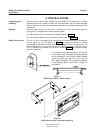
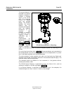
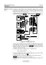
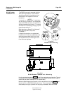
The G40A is required when a Gyro Compass with geared synchro or stepper
signal output is connected to AP45. The unit shall be mounted not more than two
meters from the AP45 control unit. This is to avoid voltage drop and reduce
interference via the interconnecting cables.
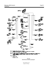
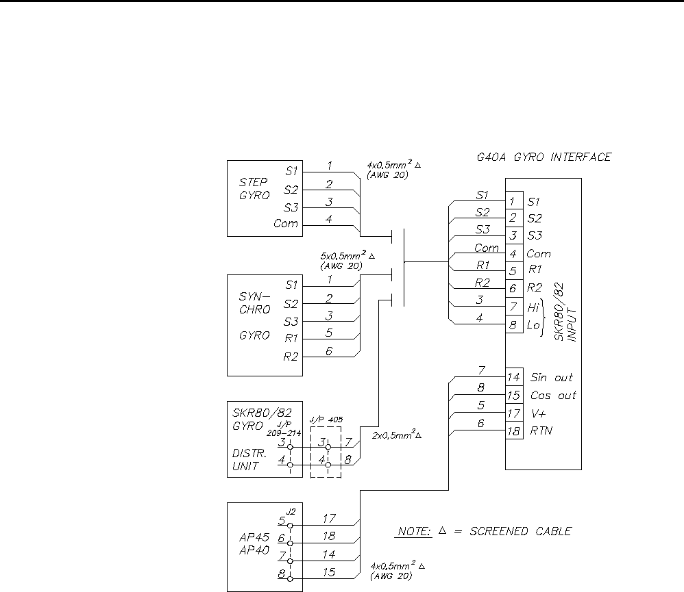
All cable conductors are terminated in screw terminals on the G40A PCB. For
cabling and connections see Fig. 5-9. For screen termination, see Fig. 5-22.
Fig. 5-9
G40A Gyro Interface Connections
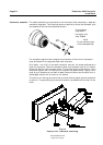
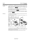
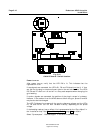
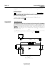
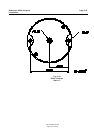
There are also three plug-in straps on the PCB, one for each phase. The position of
the straps makes the G40A to operate from either positive or negative step-
signals. For setting of the straps, refer to Fig. 5-10. The shown strap position
enables step signals with positive common. For negative common, insert strap
vertically, A1-A3, A2-A4 and so on.
In addition a DIP switch is included. Switch no. 1 sets gear ratio:
360:1 = switch to 0 (OFF)
90:1 = switch to 1 (ON)
The remaining switches 2, 3 and 4 are for test purpose only and shall be 0 (OFF)
for normal use. Refer to table on page 7-3.
For SKR80/82 current loop, switch no. 2 shall be set to ON, the others to OFF.
Fig. 5-10 shows the location of the switches and LED's.
The potentiometer VR1 is factory set to 2.5V reference voltage, and should not be
readjusted.
G40A Gyro Interface
Unit